
J
Jennifer HenryAug 14, 2025
How to fix a Bosch Control Unit when the light is constantly red?
- SSean BarronAug 14, 2025
If your Bosch Control Unit light is constantly red, this indicates an internal fault. To resolve this, replace the module.
 Loading...
How to fix a Bosch Control Unit when the light is constantly red?
If your Bosch Control Unit light is constantly red, this indicates an internal fault. To resolve this, replace the module.
What to do if Bosch MM100 is constantly OFF?
If your Bosch Control Unit is constantly off, there might be several reasons. First, ensure the coding card is properly set. Then, check if the power supply has been interrupted and switch it on. Also, a defective fuse could be the cause, so replace it after switching off the power supply. Finally, inspect the BUS connection for a short circuit and repair if necessary.
Why is the green light flashing on my Bosch Control Unit?
If the green light is flashing on your Bosch Control Unit, it could be due to exceeding the maximum cable length for the BUS connection. Try making the BUS connection shorter. Alternatively, a fault might be shown on the user interface display; consult the user interface instructions and the service manual for troubleshooting.
| Brand | Bosch |
|---|---|
| Model | MM100 |
| Category | Control Unit |
| Language | English |
Explains warning triangle symbols and safety keywords like NOTICE, CAUTION, WARNING, DANGER.
Provides guidelines for competent persons on reading instructions, observing safety, and following regulations.
Covers intended use, installation responsibilities, electrical work, user handover, and frost protection advice.
Highlights critical safety notices: risk of scalding, floor damage from underfloor heating, and system damage.
Lists items included in the standard delivery package.
Provides key technical specifications like measurements, conductor cross-section, and voltage ratings.
Specifies how to clean the product enclosure using a damp cloth.
Details optional accessories for various heating circuits and cylinder primary circuits.
Covers mounting the module on a wall or rail and installing the flow temperature sensor.
Details for connecting the BUS connection and temperature sensor on the extra-low voltage side.
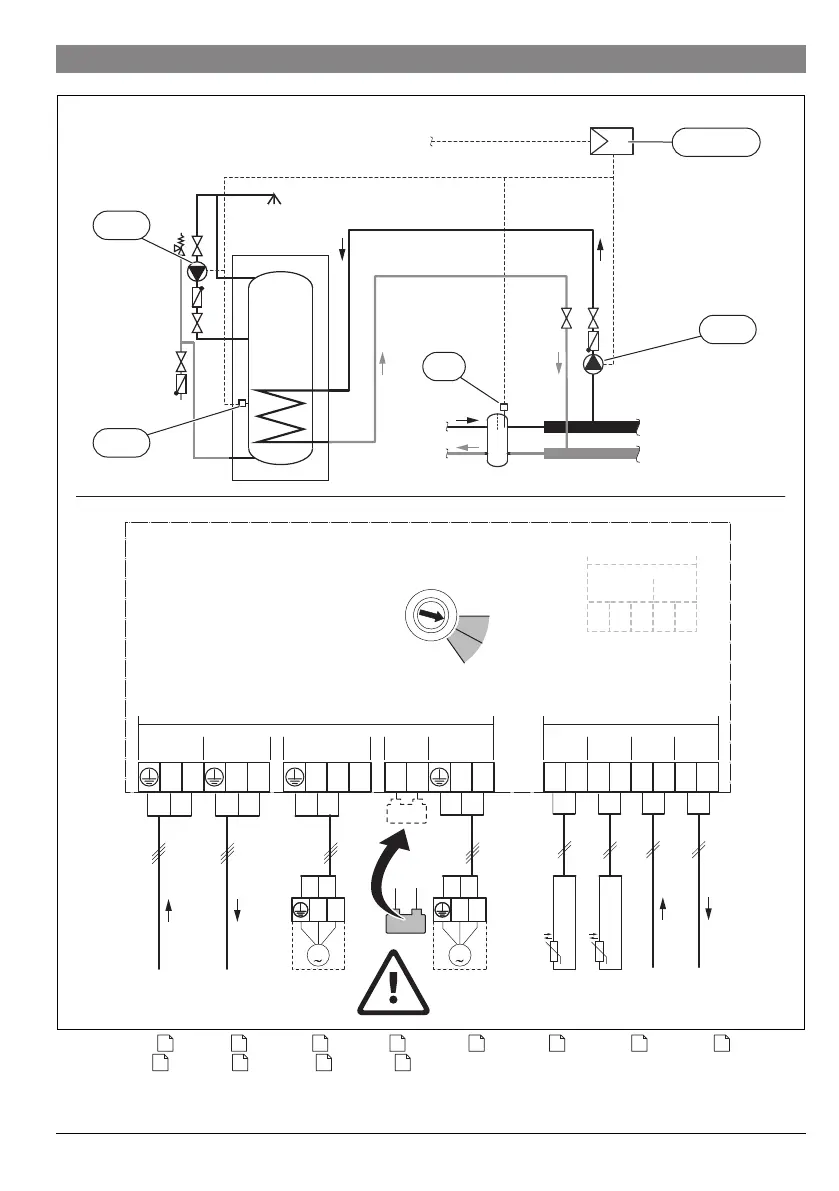
Instructions for connecting mains voltage power supply, pump, and mixing valve.
Provides schematic hydraulic diagrams and system examples for module connections.
Explains how to set the code switch for module identification and system configuration.
Procedure for assigning a module to a heating circuit and setting up the user interface.
Procedure for assigning a module to a cylinder primary circuit and setting up the user interface.
Describes module operating states (OFF, red, flashing) and their corresponding troubleshooting steps.
Details the company's commitment to environmental protection, packaging recycling, and product disposal.