1 | Overview
3.4 | Wire to the POPIT devices
To show the fi rmware version using an LED fl ash pattern:
- If the optional tamper switch is installed:
With the enclosure door open, activate the tamper switch
(push and release the switch).
- If the optional tamper switch is NOT installed:
Momentarily short the tamper pins.
Refer to Figure 5.1 for an example of fl ash pattern
s.
5 | Show the fi rmware version
Figure 5.1: Firmware LED fl ash patterns
When the tamper switch is activated (closed to open), the
heartbeat LED stays OFF for 3 sec before indicating the
fi rmware version. The LED pulses the major, minor, and
micro digits of the fi rmware version, with a 1 sec pause after
each digit.
Flashing patterns do not start until the tamper is open (short
is removed). In the following example, the version 1.4.3
shows as LED fl ashes:
[3 sec pause] *___****___*** [3 sec pause, then normal
operation].
4 | LED descriptions
The module includes one blue heartbeat LED to indicate
that the module has power and to indicate the module’s
current state. Refer to Table 4.1.
Flash Pattern Function
Flashes once
every 1 sec
Normal state. Indicates normal operation
state.
3 quick fl ashes
every 1 sec
x3
Communication error state. Indicates
(the module is in a “no communication
state”) resulting in an SDI2
communication error.
ON Steady LED trouble state. Module is not
powered (for OFF Steady only), or some
other trouble condition prohibits the
module from controlling the heartbeat
LED.
OFF Steady
Table 4.1: LED descriptions
3.3 | Wire to the control panel
You can connect modules to the SDI2 data bus by parallel wire
run from the control panel to each module, wire from module to
module, or a combination of the two techniques. Refer to
Figure 3.4.
Refer to Figure 3.4 to wire a zone expansion loop. Wire
resistance on each sensor loop must be less than 100 Ω with
the detection devices connected. The terminal strip supports
12 to 22 AWG (2.0 to 0.65 mm) wires.
+ + - -
TMPR
POPEX
- - + + - +
- - + + - +
1 2
3
3
4
5
4
6
Figure 3.4: Wiring a zone expansion loop
Callout ― Description
1 ― B299
2 ― POPIT module (D9127U/T shown)
3 ― D9127 sensor loop
4 ― 33 kΩ EOL resistor (P/N: 15-03130-022)
5 ― POPEX loop 2 (electrically identical to loop 1)
6 ― POPEX loop 1 (electrically identical to loop 2)
2.1 | Valid addresses and point numbers per
control panel
Valid B299 addresses are dependant on the number of points
allowed by a particular control panel.
Control panel Valid B299
addresses
Corresponding point
numbers
B9512G
B9512G-E
0 - 5 9 - 99, 100 - 199, 200 -
299, 300 - 399, 400 - 499,
500 - 599
B8512G
B8512G-E
0 9 - 99
3 | Installation
Set the address switch for the proper address and then install
the module into the enclosure. Wire the module to the control
panel.
CAUTION!
Remove all power (AC and battery) before making any
connections. Failure to do so might result in personal
injury and/or equipment damage.
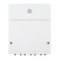
3.1 | Mount the module in the enclosure
Mount the module into the enclosure’s 3-hole mounting pat-
tern using the mounting screws and mounting bracket. Refer
to Figure 3.1.
Figure 3.1: Mounting the module in the enclosure
Callout ― Description
1 ― Module with mounting bracket installed
2 ― Enclosure
3 ― Mounting screws (3)
NOTICE!
Use either the terminal strip wiring or interconnect
wiring connector to the control panel. Do not use
both. When connecting multiple modules, you can
combine terminal strip and interconnect wiring
connectors in series.
SDI2
RESET
1
2
3
Callout ― Description
1 ― Bosch control panel
2 ― Innerconnect cable (P/N: F01U79745, included)
3 ― B299 POPEX module
Figure 3.3: SDI2 innerconnect cable wiring from control panel
to B299
Use the control panel terminals labeled R, Y, G, B (PWR, A, B,
COM) when wiring to the module. Connect them to the module
terminals labeled R, Y, G, B (PWR, A, B, COM). You can also use
the SDI2 innerconnect cable. Refer to Figures 3.2 and 3.3.
2 | SDI2 address settings
The address switch determines the address for the module.
The control panel uses the address to establish communication
between itself and the module. The address also determines
the associated point numbers. Refer to Section 6 Confi guration
for information related to the address switch. Use a slotted
screwdriver to set the address switch.
NOTICE!
The module reads the address switch setting during
power up. If you change the switches after you apply
power to the module, cycle the power to the module in
order for the new setting to be enabled.
Set the address switch per the control panel confi guration. If
multiple B299 modules reside on the same system, each B299
module must have a unique address. Figure 2.1 shows the
address switch settings for address 0.
Figure 2.1: Address switch
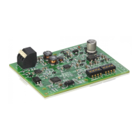
The B299 POPEX Module is an SDI2 compatible, POPIT
expansion module that communicates to the control panel
over the SDI2 bus. The B299 supports up to 100 POPIT
devices by wiring to the POPEX terminal strip and providing
one or two addressable POPIT busses.
1
2
3
4
5
6
7
Figure 1.1: POPEX module
Callout ― Description
1 ― 3-hole mounting pattern
2 ― Address switch
3 ― SDI2 interconnect wiring connectors (to control panel
or additional modules)
4 ― SDI2 terminal strip (to control panel or additional
modules)
5 ― Heartbeat LED (blue)
6 ― Tamper switch (optional) connector
7 ― POPEX terminal strip (POPIT Bus))