9
English
BASS
LEVEL
Ch2Ch1
OFF
+10
OFF
+10
ZONE 1 ZONE 2
REMOTE
VOLUME
ZONE 1 ZONE 2
LINE OUTPUT
+-+-
INPUT
MODE
2Ch
dual
mono mono
+-+-+-
70/100V
ZONE1
4-16 Ω
ZONE 2
4-16 Ω
XFR
CT
MODE
POWER AMPLIFIER
70/100V 2 Ch
BRIDGED
LEVEL
Zone 2Ch2Ch1
0 0 0-40 dB -40 dB -40 dB
-10-10 -10
-6 -6 -6
Ch1 Ch2
INPUTS A
+- +-
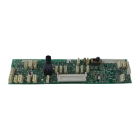
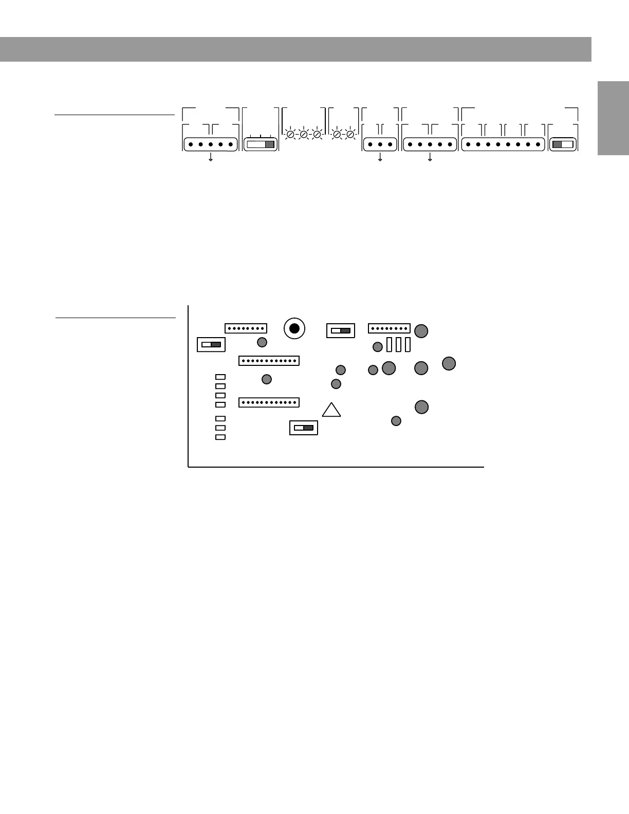
AmPlus 100 amplifier controls (cont’d)
Figure 3 (cont’d)
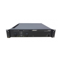
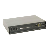
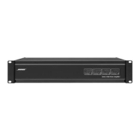
AmPlus 100 amplifier
controls
All About The AmPlus
TM
100 Amplifier
Figure 4
Internal remote volume
switch
C
1 Remote
2 Remote
High Pass
Filter
Mix
EQ 1
EQ 2
Bass Level –
Use the bass level potentiometers (pots) to increase the output level
between 50Hz
and 150Hz. This is useful for compensating for poor bass cabinet
loading or high levels of low-frequency ambient noise. The Channel 1 and Channel 2
pots are active in all modes of operation.
Remote Volume – When using the amplifier to power one listening zone, connect the
remote control unit to the zone 1 (+) pin and the ground pin. Set the internal remote
volume switch (Figure 4) to 1_REMOTE. When using the AmPlus 100 amplifier for 2-
zone applications, connect a second remote to the zone 2 (+) pin and ground pin. Set
the internal remote volume switch to 2_REMOTE.
Line Outputs – Both line output responses are flat (regardless of whether or not you
have installed active equalizer cards). The remote volume control affects the line
output levels. Both outputs are active in stereo mode. Only zone 1 is active in dual
mono and mono modes.
Power Amplifier Outputs – The 70/100V output becomes active when the amp
mode switch is in the 70/100V
position. In this setup, both AmPlus 100 amplifier
channels are bridged and provide
up to 100W to the 70/100V speaker(s).
When the amp mode is in the 2-channel position and a jumper is placed across the
XFR CT pins, 50W is available at the 70/100V output and 65W is available at the
channel 2 output.
With the amp mode switch in the 2-channel position, both Channel 1 and Channel 2
supply 65W into a minimum load of 4Ω.
Internal High Pass Switch – When this switch is in the “HPF ON” position, frequen-
cies below 150Hz are attenuated at 18dB/OCT. This low-frequency roll-off occurs on
Channel 1 only. Use this switch for bandlimiting high-frequency speakers connected
to Channel 1 in a bi-amplified system.
 Loading...