70
Rear Panel Controls and Connections
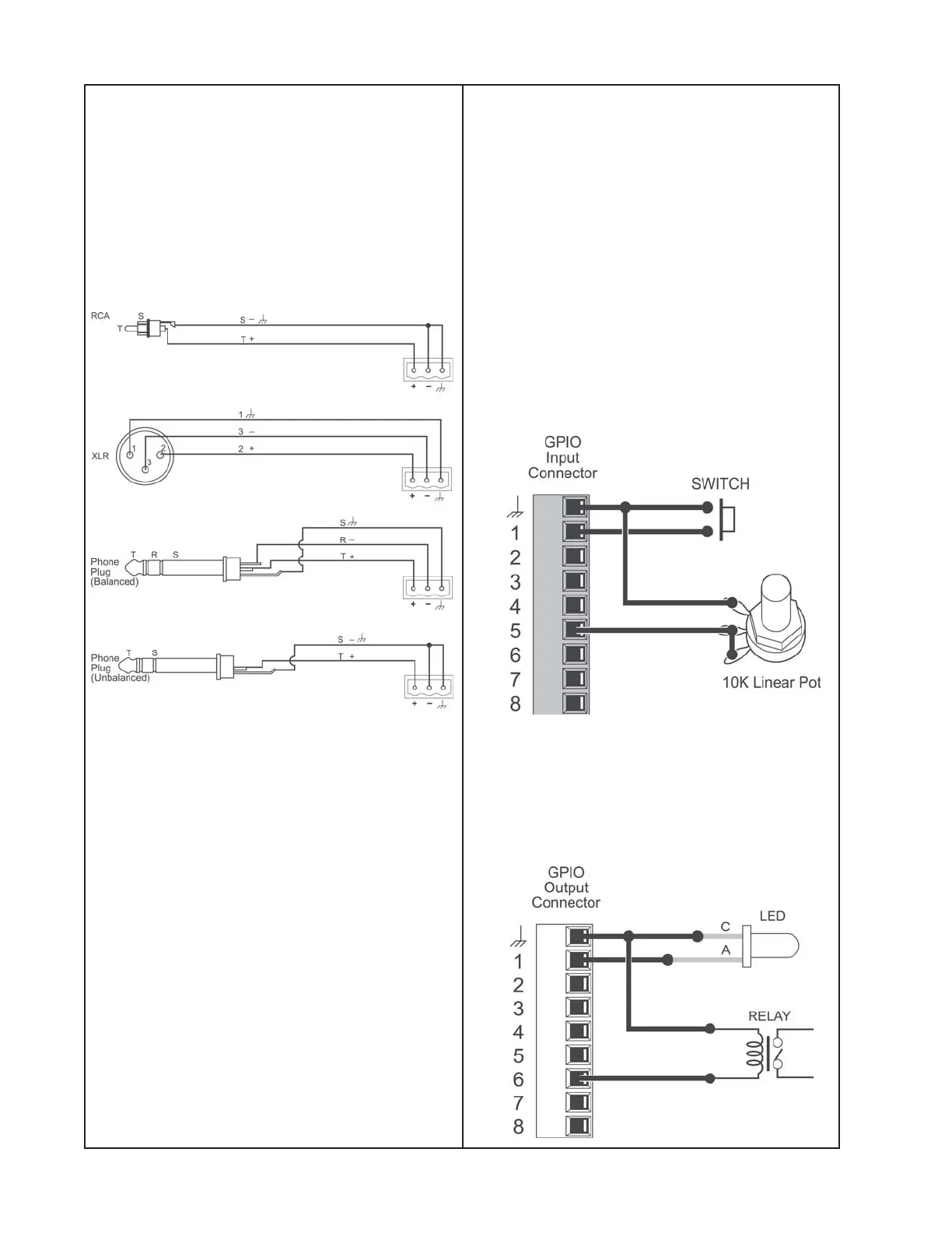
Mic/Line Inputs
The ESP-88 (base model) includes two “4x4”
Mic/Line cards. Each of these cards occupy
two slots. The input connectors (green) and
the input LEDs appear in the first slot. The
output connectors (orange) and LEDs
appear in the second slot. A microphone or
line level audio source can be connected to
the Mic/Line inputs using one of the following
cable types.
General Purpose Inputs/Outputs
The ESP-88 (base model) includes one
GPIO card in slot 1 providing eight control
inputs and eight control outputs. A second
card can be added to GPIO slot 2.
Inputs
Switches and potentiometers can be con-
nected to the control inputs to control var-
ious functions in the system. For example,
simple ON/OFF switches can be connected
and then programmed to invoke presets,
select scenes, or invoke a snapshot of a
control. Likewise, 10k linear potentiometers
can be connected to control gains in the
system.
Inputs contain a 5k ohm pull-up resistor
allowing SPST switches to be wired from
input to ground. Potentiometers can be
wired in series from the control input to
ground.
Outputs
LEDs and relays can be connected to gen-
eral purpose outputs to indicate state
changes in the system (e.g. preset or scene
changes).

 Loading...