7
1.6 Reference a dB meter and measure
the response of the EQ card according to
the Surface Frequency Response chart.
2. Distortion Test
2.1 Apply a 780 mVrms, 1 kHz signal to the
input jack of the amplifier channel under
test.
2.2 Measure the distortion level at the
output of the amplifier. It should be ≤ 0.1%
THD.
TEST PROCEDURES
3. Distortion Test
3.1 Apply a 780 mVrms, 1 kHz signal to the
input jack of the amplifier channel under
test.
3.2 Measure the distortion level at the
output of the amplifier. It should be ≤ 0.1%
THD.
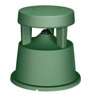
FreeSpace
®
360 Surface Loudspeaker
Test Setup Parameters
1. Install the Equalizer card under test into
one of the Equalizer card jacks located on
the Input Module of the Bose
®
1600 or
1800 Series amplifier, and perform the
following tests. Refer to the 1800V service
manual supplement part number 181812-
S2 for more information.
2. On the amplifier Input Module, place
switch SW1 to the NORM position. Place
switch S2 to the FULL BANDWIDTH
position.
3. The input voltage shall be the actual
input voltage present at the input, not the
open circuit generator input.
1. Surface Equalizer PCB Frequency
Response Test
1.1 Apply a 100 mVrms, 1kHz signal to the
input jack of the amplifier channel under
test.
1.2 Adjust the amplifier volume controls to
maximum. No EQ card installed.
1.3 Reference a dB meter to the output of
the amplifier.
1.4 Shut off the amplifier and insert the EQ
card according to the assembly procedure.
1.5 Turn on the amplifier and measure the
gain. There should be a +1.0 ± 1.0 dB
change in gain at the output.
Surface Frequency Response
Frequency Output Level
30 Hz -8.8 dB ± 1.5 dB
90 Hz +7.2 dB ± 1.5 dB
180 Hz +11.0 dB ± 1.5 dB
900 Hz +0.2 dB ± 1.5 dB
1000 Hz Reference
2000 Hz +0.4 dB ± 1.5 dB
5000 Hz +6.7 dB ± 1.0 dB
10000 Hz +17.9 dB ± 2.5 dB
 Loading...