System Configurations
The Bose
®
Panaray
®
system provides a
flexible, building-block approach to fit
the sound reinforcement requirements of
many types of applications, from night
clubs to cathedrals. Detailed installation
and system design guidelines for the
Panaray System are provided in the
Panaray System Owner's Guide. For
illustrative purposes, here are some
typical system configurations.
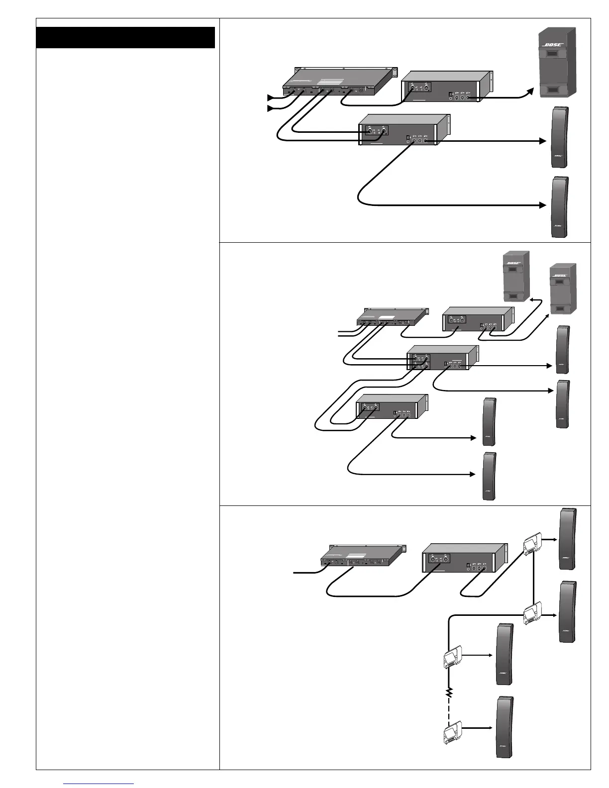
Figure 1 shows a block diagram of the
basic Panaray System, consisting of one
502
®
B, two 502A's, one 502C, and three
channels of amplication for a stereo
system. This system provides 115dB
SPL @ 1 m average acoustic output.
Additional low frequency output can
easily be achieved by locating the
cabinet against large hard surfaces.
(There is also bass volume adjustment
possible through the rear-panel control
on the 502C).
Figure 2 illustrates how components can
be added to the basic Panaray system to
achieve a variety of SPL or coverage
requirements. One example of an
expanded system would be a small disco
dance area. In this application, four
arrays at the outer corners of the dance
floor, plus two 502B's on the floor
adjacent to the dance area, will deliver
approximately 118dB SPL average, with
130dB SPL peaks, all components driven
at maximum recommended amplifier
power.
Figure 3 shows how the Panaray compo-
nents can be interconnected for a voice-
only paging system. This system is ideal
for applications where voice reinforce-
ment is needed over a large area, such
as an airport terminal or a train station.
Through the use of the Bose CVT-5
constant voltage transformer, multiple
502A's can be installed in a 70/100V
constant voltage distributed system.
(This system operates from 130Hz and
above only, and is not recommended for
use where music is an integral part of the
program material).
Figure 1: Basic Panaray system
®
®
502 C
SER. NO. D.O.M.
CH 1
INPUT LEVEL
–10 +4
INPUT
CH 2
INPUT LEVEL
–10 +4
MODE
4
1
2
3
PROTECTED BY U.S. PATENT 3,038,964
REFER TO YOUR INSTRUCTION MANUAL FOR PROPER INSTALLATION
AND OPERATING PROCEDURES. INCORRECT WIRING MAY RESULT IN
CAUTION AVIS
RISK OF ELECTRICAL SHOCK
DO NOT OPEN
RISQUE DE CHOC ELECTRIQUE
NE PAS OUVRIR
WARNING:
TO REDUCE THE RISK OF FIRE OR ELECTRICAL SHOCK
DO NOT EXPOSE THIS EQUIPMENT TO RAIN OR MOISTURE.
MODE SWITCH GUIDE
POSITION OPERATING MODE
4
2-WAY WITH LOW FREQUENCY OPTION
(NOT USED)
3
STANDARD 2-WAY (WITH 502B)
2
VOICE ONLY/FULL RANGE (WITH 502A)
1
HIGH
FREQ
OUTPUT
CH 1 CH 2
LOW FREQ
LEVEL
0
.
.
.
.
.
.
.
+3
-18
BOSE CORPORATION, FRAMINGHAM, MA 01701-9168
ENGINEERED AND MANUFACTURED IN U.S.A.
OUTPUT MODE
NORM SUM
LOW
FREQ
OUTPUT
CH 1 CH 2
230V
~
AC
50/60Hz 12W
INPUT B
INPUT B INPUT A
BRIDGE
INPUT A
220 V
~
MADE IN USA
CAUTION
In order to grant a secure operation do not mount the amplifier in
a fully closed housing. To preven electric shock, do not remove
cover. Disconnect power line in case of servicing.
ACHTUNG:
Um sichere Funktion zu gewährielsten, Gerät nicht in vollständig
geshlossenes Gehäuse einbauen. Abdeckung während des
Betriebes nicht entfernen. Bor Offnen des Gerätes Netzstecker
ziehen.
Bose Corporation, Framinhman 01701, Mass, U.S.A.
Serial No.:
Made in Germany
OUTPUT B BRIDGE OUTPUT OUTPUT A
ON
OFF
L
R
High
Frequency
Output
Low Frequency
Output
Amplifier
Amplifier
L
R
L
R
502A
(Left)
502A
(Right)
502B
From
Pre-
amplifier
®
®
Figure 2: Expanded Panaray system
502A
Constant-Voltage
502 C
INPUT B
INPUT B INPUT A
BRIDGE
INPUT A
220 V
~
MADE IN USA
CAUTION
In order to grant a secure operation do not mount the amplifier in
a fully closed housing. To preven electric shock, do not remove
cover. Disconnect power line in case of servicing.
ACHTUNG:
Um sichere Funktion zu gewährielsten, Gerät nicht in vollständig
geshlossenes Gehäuse einbauen. Abdeckung während des
Betriebes nicht entfernen. Bor Offnen des Gerätes Netzstecker
ziehen.
Bose Corporation, Framinhman 01701, Mass, U.S.A.
Serial No.:
Made in Germany
OUTPUT B BRIDGE OUTPUT OUTPUT A
ON
OFF
SER. NO. D.O.M.
CH 1
INPUT LEVEL
–10 +4
INPUT
CH 2
INPUT LEVEL
–10 +4
MODE
4
1
2
3
PROTECTED BY U.S. PATENT 3,038,964
REFER TO YOUR INSTRUCTION MANUAL FOR PROPER INSTALLATION
AND OPERATING PROCEDURES. INCORRECT WIRING MAY RESULT IN
CAUTION AVIS
RISK OF ELECTRICAL SHOCK
DO NOT OPEN
RISQUE DE CHOC ELECTRIQUE
NE PAS OUVRIR
WARNING:
TO REDUCE THE RISK OF FIRE OR ELECTRICAL SHOCK
DO NOT EXPOSE THIS EQUIPMENT TO RAIN OR MOISTURE.
MODE SWITCH GUIDE
POSITION OPERATING MODE
4
2-WAY WITH LOW FREQUENCY OPTION
(NOT USED)
3
STANDARD 2-WAY (WITH 502B)
2
VOICE ONLY/FULL RANGE (WITH 502A)
1
HIGH
FREQ
OUTPUT
CH 1 CH 2
LOW FREQ
LEVEL
0
.
.
.
.
.
.
.
+3
-18
BOSE CORPORATION, FRAMINGHAM, MA 01701-9168
ENGINEERED AND MANUFACTURED IN U.S.A.
OUTPUT MODE
NORM SUM
LOW
FREQ
OUTPUT
CH 1 CH 2
230V
~
AC
50/60Hz 12W
502A
CVT-5
CVT-5
CVT-5
502A
502A
CVT-5
High Frequency
From
®
®
®
®
®
®
®
®
Figure 3: Distributed voice-only system
High Frequency
Amplifier One
Bass Amplifier
502 C
502A
502A
502B
®
®
®
®
502A
502A
®
®
®
®
502B
INPUT B
INPUT B INPUT A
BRIDGE
INPUT A
220 V
~
MADE IN USA
CAUTION
In order to grant a secure operation do not mount the amplifier in
a fully closed housing. To preven electric shock, do not remove
cover. Disconnect power line in case of servicing.
ACHTUNG:
Um sichere Funktion zu gewährielsten, Gerät nicht in vollständig
geshlossenes Gehäuse einbauen. Abdeckung während des
Betriebes nicht entfernen. Bor Offnen des Gerätes Netzstecker
ziehen.
Bose Corporation, Framinhman 01701, Mass, U.S.A.
Serial No.:
Made in Germany
OUTPUT B BRIDGE OUTPUT OUTPUT A
ON
OFF
SER. NO. D.O.M.
CH 1
INPUT LEVEL
–10 +4
INPUT
CH 2
INPUT LEVEL
–10 +4
MODE
4
1
2
3
PROTECTED BY U.S. PATENT 3,038,964
REFER TO YOUR INSTRUCTION MANUAL FOR PROPER INSTALLATION
AND OPERATING PROCEDURES. INCORRECT WIRING MAY RESULT IN
CAUTION AVIS
RISK OF ELECTRICAL SHOCK
DO NOT OPEN
RISQUE DE CHOC ELECTRIQUE
NE PAS OUVRIR
WARNING:
TO REDUCE THE RISK OF FIRE OR ELECTRICAL SHOCK
DO NOT EXPOSE THIS EQUIPMENT TO RAIN OR MOISTURE.
MODE SWITCH GUIDE
POSITION OPERATING MODE
4
2-WAY WITH LOW FREQUENCY OPTION
(NOT USED)
3
STANDARD 2-WAY (WITH 502B)
2
VOICE ONLY/FULL RANGE (WITH 502A)
1
HIGH
FREQ
OUTPUT
CH 1 CH 2
LOW FREQ
LEVEL
0
.
.
.
.
.
.
.
+3
-18
BOSE CORPORATION, FRAMINGHAM, MA 01701-9168
ENGINEERED AND MANUFACTURED IN U.S.A.
OUTPUT MODE
NORM SUM
LOW
FREQ
OUTPUT
CH 1 CH 2
230V
~
AC
50/60Hz 12W
INPUT B
INPUT B INPUT A
BRIDGE
INPUT A
220 V
~
MADE IN USA
CAUTION
In order to grant a secure operation do not mount the amplifier in
a fully closed housing. To preven electric shock, do not remove
cover. Disconnect power line in case of servicing.
ACHTUNG:
Um sichere Funktion zu gewährielsten, Gerät nicht in vollständig
geshlossenes Gehäuse einbauen. Abdeckung während des
Betriebes nicht entfernen. Bor Offnen des Gerätes Netzstecker
ziehen.
Bose Corporation, Framinhman 01701, Mass, U.S.A.
Serial No.:
Made in Germany
OUTPUT B BRIDGE OUTPUT OUTPUT A
ON
OFF
INPUT B
INPUT B INPUT A
BRIDGE
INPUT A
INPUT B
INPUT B INPUT A
BRIDGE
INPUT A
220 V
~
MADE IN USA
CAUTION
In order to grant a secure operation do not mount the amplifier in
a fully closed housing. To preven electric shock, do not remove
cover. Disconnect power line in case of servicing.
ACHTUNG:
Um sichere Funktion zu gewährielsten, Gerät nicht in vollständig
geshlossenes Gehäuse einbauen. Abdeckung während des
Betriebes nicht entfernen. Bor Offnen des Gerätes Netzstecker
ziehen.
Bose Corporation, Framinhman 01701, Mass, U.S.A.
Serial No.:
Made in Germany
OUTPUT B BRIDGE OUTPUT OUTPUT A
ON
OFF
High Frequency
Amplifier Two
 Loading...