Service&TroubleshootingGuide- HomeGeneratorSystems
Model1938(lOkW)GeneralInformation
St_an_
Power During Fault Conditions
Whenever the Home Generator System is in an
uncorrected fault condition, the automatic transfer switch
resets to UTILITY POWER. This means that when utility
power is restored, it will automatically be applied to all the
circuits in the home.
Control Module Assembly (CMA)
The Control Module Assembly (CMA) is a printed circuit
board containing all the logic circuits that operate and
protect the generator. It is located inside the generator
enclosure behind the AIR INTAKE DOOR. It is the control
center of the generator. Its functions depend on the input
from various circuits throughout the standby installation.
Before replacing the CMA, all other circuits must be tested
to ensure proper operation. When a failure in the CMA has
been determined, the CMA must be replaced as a complete
assembly because its individual parts are not serviceable.
The functions of the CMA include:
• Battery Trickle Charge
• Set Exercise Timer
• Manual Start
• Sensing Utility Voltage
• Automatic Start, in event of utility failure
• Automatic generator power transfer.
• Automatic Engine Cool-Down Timer
• Fault Detection and Automatic Shutdown
• Fault Light Indication (Diagnostic LED)
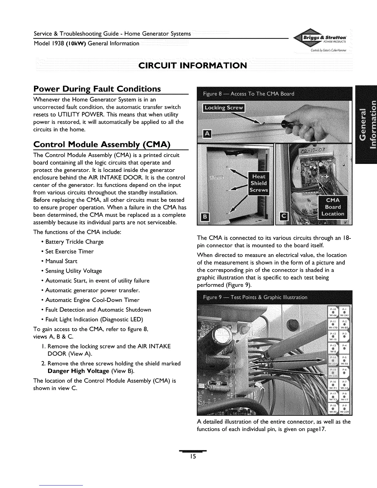
To gain access to the CMA, refer to figure 8,
views A, B & C.
I. Remove the locking screw and the AIR INTAKE
DOOR (View A).
2. Remove the three screws holding the shield marked
Danger High Voltage (View B).
The location of the Control Module Assembly (CMA) is
shown in view C.
The CMA is connected to its various circuits through an 18-
pin connector that is mounted to the board itself.
When directed to measure an electrical value, the location
of the measurement is shown in the form of a picture and
the corresponding pin of the connector is shaded in a
graphic illustration that is specific to each test being
performed (Figure 9).
A detailed illustration of the entire connector, as well as the
functions of each individual pin, is given on page 17.
15
 Loading...