Home
Briggs & Stratton
Engine
MS-1055
Briggs & Stratton MS-1055 User Manual
4
of 1
of 1 rating
128 pages
Give review
Manual
Specs
To Next Page
To Next Page
To Previous Page
To Previous Page
Loading...
6
4
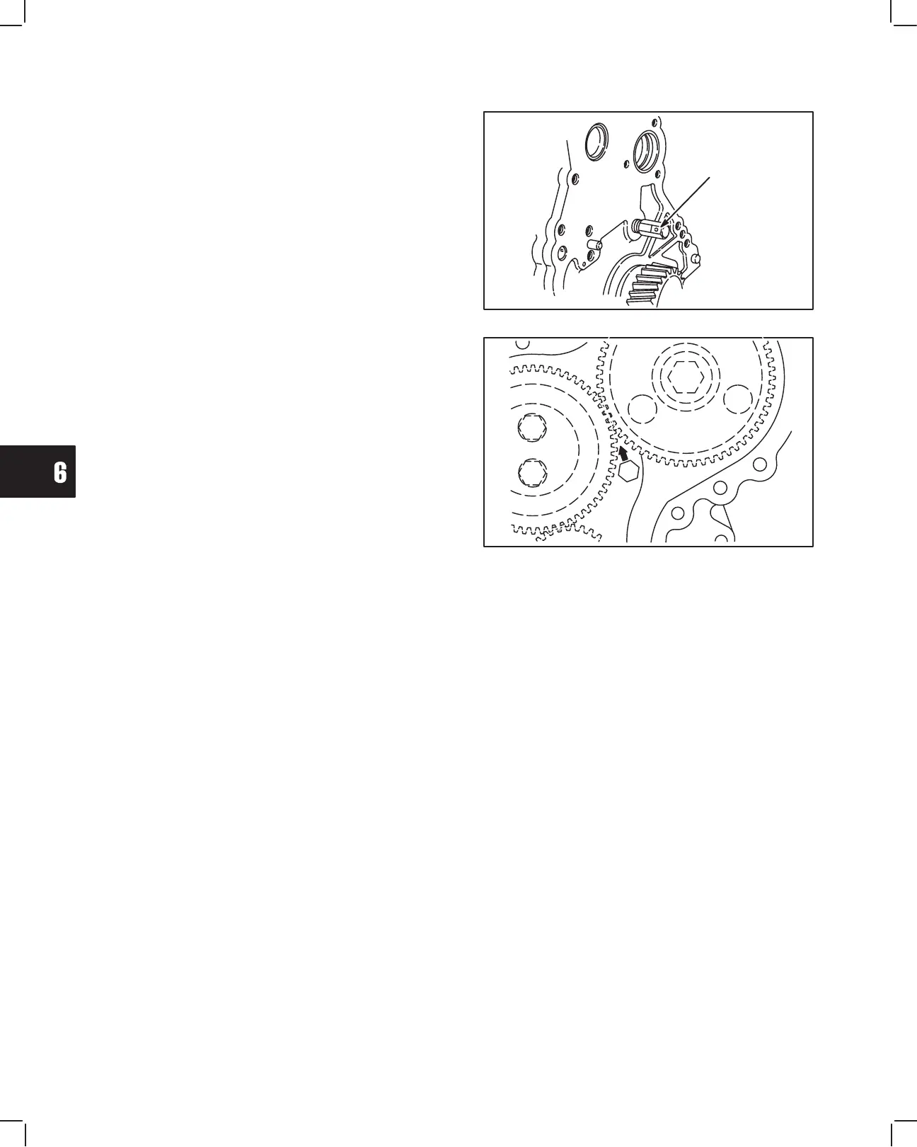
CYLINDER BLOCK INSPECTION AND REP
AIR
2.
Remove timing gear oil nozzle, Fig. 1
1.
Fig. 1
1 – Removing Oil Nozzle
OIL NOZZLE
3.
When re-installing oil nozzle, oil hole must be
positioned at 45
°"
angle, pointing towards idler
gear
, Fig. 12.
Fig. 12 – Installing Oil Nozzle
IDLER GEAR
43
45
Table of Contents
General Information
2
Engine Model and Type Number
2
Engine Identification Numbers
2
Engine Serial Number
2
In the Interest of Safety
3
Engine Views
4
Engine Specifications
5
Injection Pump Timing
8
Engine Date Code before 99010100
8
Engine Date Code after 98123100
8
Injector Pump Identification
9
Engine Speed Specification Chart
9
Maintenance Schedule
12
Overhead Valve Train
13
Cylinder Head and Valves
13
Remove Cylinder Head
14
Remove Water Pump and Exhaust Manifold
14
Remove Valve Cover
14
Remove Fuel Lines
14
Remove Glow Plugs and Injectors
15
Set Cylinder No. 1 at TDC
15
Remove Rocker Arm Assembly and Push Rods
15
Loosen Cylinder Head Bolts
15
Remove Valve Stem Seal
16
Disassemble Cylinder Head
16
Remove Valves
16
Cylinder Head Components
16
Check Cylinder Head for Distortion
17
Check Combustion Chamber
17
Remove Combustion Chamber
17
Check and Repair Valve Guides
18
Check Valve Guide Bushing
18
Remove Valve Guide Bushing
18
Valve Seat Dimensions
19
Installing Valve Guide Bushing
19
Valve Dimensions
19
Valves and Seats
19
Disassemble Rocker Arm Shaft
20
Check Valve Stem Cap
20
Check Valve Springs
20
Rocker Arm Components
20
Checking Rocker Arm and Shaft
21
Assemble Rocker Arm Shaft
21
Assemble Cylinder Head
22
Install Valve Stem Seals
22
Install Cylinder Head Gasket
23
Install Cylinder Head
23
Install Valve Spring Seats and Valves
23
Install Valve Springs
23
Install Push Rods
24
Install Rocker Arm Assembly
24
Install Intake Manifold
24
Install Glow Plugs and Injectors
24
Install Water Pump
25
Install Water Pump Pulley and Fan
25
Install Exhaust Manifold
25
General Assembly
25
Adjust Valves
26
Adjust Valve Clearances
26
Install Valve Cover
26
Timing Gears and Gear Case
27
Removing Timing Gear Cover and Gears
28
Remove Fuel Delivery Lines
28
Removing Oil Pan
28
Removing Crankshaft Pulley
28
Checking Idler Gear and Shaft
29
Checking Idler Gear Backlash
29
Removing Oil Pump Gear
29
Checking Gears
29
Remove Gear Case
30
Removing Injector Pump
30
Removing Timing Gear Case
30
Replace Timing Gear Cover Oil Seal
31
Assemble Timing Gear Case and Gears
31
Installing Oil Pump Rotor
31
Installing Timing Gear Case
31
Installing Timing Gear Cover
32
Torque Screws
32
Aligning Timing Marks – Typical
32
Installing Idler Gear Shaft
32
Installing Crankshaft Pulley
33
Installing Oil Pan
33
Installing Fuel Delivery Lines
33
Flywheel and Rear Seal Retainer
34
Removing Pan and Flywheel
34
Removing Flywheel
34
Installing Rear Seal Retainer and Flywheel
35
Remove Rear Seal Retainer
35
Replacing Oil Seal
35
Install Oil Pan
36
Install Flywheel
36
Install Oil Pan with New Gasket
36
Cylinder Block Disassembly
37
Engine Stand
38
Mounting Plate
38
Engine Stand Fixture
38
Removing Camshaft
39
Removing Alternator
39
Removing Valve Lifters
39
Removing Starter and Bracket
39
Removing Connecting Rod Assembly
40
Removing Main Bearing Caps
40
Removing Crankshaft
40
Cylinder Block Inspection and Repair
41
Checking Cylinder Block
41
Cylinder Block Height
41
Replacing Camshaft Bearing
42
Checking Cam Bearing
42
Checking Valve Lifter and Bore
42
Checking Cylinder Bore
42
Replacing Camshaft Plug
43
Installing Cam Bearing
43
Removing Camshaft Plug
43
Installing Camshaft Plug
43
Removing Oil Nozzle
44
Installing Oil Nozzle
44
Checking Run-Out
45
Checking Journals
45
Checking Crankshaft
45
Crankshaft, Camshaft and Bearings
45
Checking Main Bearing Clearances
46
Checking Timing Gear
46
Install Plastigage
46
Torque Bearing Cap
46
Checking Connecting Rod Bearing Clearances
47
Checking Crankshaft End Play
47
Torque Rod Cap
47
Measure Clearance
47
Checking Camshaft Journals
48
Checking Camshaft Lobes
48
Checking Camshaft
48
Piston, Rings and Connecting Rod Inspection and Assembly
49
Disassemble Piston and Connecting Rod
49
Removing Piston Rings
49
Disassembling Piston/Connecting Rod
49
Checking Piston and Rings
50
Checking Ring Grooves
50
Checking End Gap
50
Checking Piston Pin Bore
50
Assembling Piston and Rod
51
Checking Crankpin Bearing End
51
Checking Connecting Rod
51
Checking Piston Pin Bearing
51
Assemble Piston Rings to Piston
52
Installing Piston Rings
52
Stagger Ring End Gaps
52
Cylinder Block Assembly
53
Install Crankshaft
53
Installing Upper Main Bearings
53
Installing Lower Main Bearings
53
Installing Connecting Rod Bearings
54
Installing Main Bearing Caps
54
Installing Crankshaft
54
Installing Piston and Connecting Rod
55
Installing Oil Pick-Up
55
Installing Rear Seal Retainer
55
Installing Flywheel
55
Install Timing Gear Case, Camshaft and Gears
56
Installing Gear Case
56
Installing Camshaft
56
Rotate Crankshaft
56
Aligning Timing Marks
57
Assemble Idler Gear Shaft
57
Install Alternator
58
Installing Pulley
58
Installing Timing Cover
58
Table of Contents
59
Fuel System and Related Components
59
Fuel Injection System Components
60
Injection Pump Timing Specifications
61
Injector Pump
61
Checking Injector Pump Timing
62
Removing Fuel Lines
62
Align Timing Marks
62
Install Timing Tool
62
Checking Timing
63
Install Distributor Screw
63
Loosen Pump
63
Adjusting Injector Pump Timing
63
Installing Distributor Screw
64
INJECTORS Remove Injectors
64
Checking Injectors
65
Removing Injectors
65
Injector Shim
65
Fuel Filter – General
66
Checking Spray Pattern
66
Checking Leakage
66
Install Injectors
66
Draining Water Collector
67
Change Fuel Filter
67
Checking Float Sensor
67
Checking Fuel Shut-Off Solenoid Wiring
67
Injector Pump Identification
68
Adjust Idle Speed
69
Adjust Top no Load Speed
69
Electrical System
70
Electrical System Components
72
Glow Plug System
73
Glow Plug Specifications
73
Remove Glow Plug
73
Testing Glow Plug
73
Test Equipment
73
Preheat Timer and Glow Relay
74
Testing Preheat Timer
74
Testing Glow Relay
74
Keyswitches
75
Fixed Timer Preheat Keyswitch
75
Manual Preheat Keyswitch
75
Keyswitch – Manual Preheat
75
14 Amp Charging System
76
Test Equipment
76
Regulator-Rectifier
76
Testing Alternator – AC Output
77
Testing Regulator-Rectifier – DC Output
77
DC Shunt Installation
77
Charging Indicator Circuit
78
Testing Charging Indicator Bulb and Wiring
78
Meter Setting
78
Testing Bulb and Wiring
78
40 Amp Charging System
79
Test Equipment 40 Amp Alternator
79
Testing Alternator – DC Output
79
Disassemble Alternator
80
Remove Brush Retainer
80
Remove Regulator
80
Checking Bearings
81
Remove Ball Bearing
81
Remove Brush End Housing
81
Remove Rotor
81
Install Ball Bearing
82
Checking Rotor
82
Check Brushes
82
Check Slip Ring
82
Check Regulator
83
Check Rectifier
83
Assemble Alternator
83
Installing Rotor
83
Assemble Housings
84
Install Rectifier
84
Install Regulator
84
Install Brush Cover
84
Starter System – General Information
86
Starter Current Draw Test – All
86
Test Equipment
86
Testing Starter – All
87
Starter Current Draw Test – no Load
87
No Load Starter Current Draw Test
87
Testing Starter Solenoid
88
Testing Solenoid
88
Exploded View of Starter – Typical
88
STARTER SOLENOID Test Equipment
88
Remove Solenoid
89
Remove Pinion and Clutch Assembly
89
Removing Starter Motor
89
Removing Solenoid
89
Check Pinion and Clutch Assembly
90
Assemble Pinion and Clutch Assembly
90
Assembling Roller Bearings
90
Assembling Drive Housing
90
Install Solenoid
91
Replace Solenoid Plunger and Contacts
91
Remove Plunger
91
Checking Contacts
91
Field Wire Terminal Side
92
Battery Wire Terminal Side
92
Contact Assemblies
92
Loosen Nuts
92
Disassemble Starter Motor
93
Inspect Armature Commutator
93
Inspect Brushes
93
Commutator Specifications
93
Replace Brushes – 1.0 KW Starter
94
Clean Terminals
94
Install Brushes
94
Assemble Starter Motor
95
Assembling Motor Housing and Brushes
95
Installing End Cap
95
Installing Starter Motor
95
Wiring Diagram – 14 Amp Alternator (Typical)
96
Starter System
96
Wiring Diagram – 40 Amp Alternator (Typical)
97
Lubrication System
100
Recommended SAE Viscosity Grades
100
Change Oil
101
Oil Drain Plug
101
Oil Fill Cap
101
Change Oil Filter
101
Check Oil Pressure
102
Low Oil Pressure
102
High Oil Pressure
102
Disassemble Gear Case
103
Remove Oil Pump
103
Assemble Gear Case
106
Install Oil Pump
106
Install Injector Pump
106
Cooling System
109
Checking Cooling System
110
Pressure Testing Cooling System
110
Testing Radiator Cap
110
Draining Coolant
110
Removing Thermostat – Engine Cold
111
Checking Thermostat
111
Installing Thermostat
111
Water Pump
112
Inspecting Water Pump
112
Removing Water Pump
112
Remove Hoses
112
Installing Water Pump
113
Installing Coolant Inlet and Outlet
113
Installing Fan and Pulley
113
Install V-Belt
113
Turbocharger
114
Turbocharger Lubrication System
115
Full Floating Bearing
115
Turbocharger Cooling System
116
Turbocharger Waste Gate
117
Turbocharger Pressure Control System
117
Crankcase Blow-By Recirculating System
118
Checking Waste Gate Actuator
118
Checking Waste Gate Valve
118
Servicing and Operation Information
119
Cautions on Handling Turbocharger
119
Remove Turbocharger
120
Remove Clamp
120
Disconnecting Air Intake Tube
120
Removing Air Intake Pipe
120
Disconnect Coolant Hose
121
Removing Coolant Line
121
Removing Union Screw
121
Removing Bracket Bolt
122
Removing Oil Outlet Tube
122
Removing Turbo Charger Bracket
122
Checking Turbocharger
123
Removing Turbocharger Assembly
123
Checking Turbocharger Assembly
123
Install Turbocharger
124
Installing Turbocharger Assembly
124
Installing Turbocharger Bracket
124
Installing Oil Outlet Tube
124
Installing Oil Inlet Line
125
Installing Bracket Screw
125
Installing Coolant Line
125
Install Bracket Screw
125
Install Coolant Outlet Hose
126
Install Coolant Inlet Hose
126
Installing Air Intake Pipe
126
Installing Air Intake Hose
126
Installation of Coolant Inlet Tube
127
Installing Clamp
127
Installing Tube
127
4
Based on 1 rating
Ask a question
Give review
Questions and Answers:
Need help?
Do you have a question about the Briggs & Stratton MS-1055 and is the answer not in the manual?
Ask a question
Briggs & Stratton MS-1055 Specifications
General
Brand
Briggs & Stratton
Model
MS-1055
Category
Engine
Language
English
Related product manuals
Briggs & Stratton MS-0750
85 pages
VANGUARD M490000
144 pages
Briggs & Stratton Intek
10 pages
Briggs & Stratton Classic
11 pages
Briggs & Stratton 500 Series
32 pages
Briggs & Stratton 725 Series
100 pages
Briggs & Stratton 950 Series
13 pages
Briggs & Stratton Snow Series
24 pages
Briggs & Stratton 300e Series
10 pages
Briggs & Stratton 675EXi Series
128 pages
VANGUARD Series
76 pages
Extended Life Series
28 pages
 Loading...