10
4
INJECTOR PUMP
Checking Injector Pump Timing
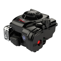
NOTE: Clean areas around fuel lines and injec-
tors to prevent any dirt from entering
injector nozzles or delivery valve ports
when fuel delivery lines are removed.
1. Remove fuel delivery lines from injector pump and
injector nozzles, Fig. 1.
Fig. 1 – Removing Fuel Lines
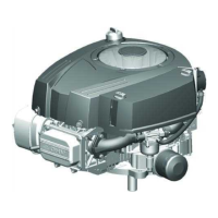
2. Set No. 1 piston at TDC:
a. Rotate crankshaft until timing mark on pulley
is aligned with reference point on timing cover,
Fig. 2.
b. If intake and exhaust valves have clearance,
No. 1 piston is at TDC – compression stroke.
c. If intake and exhaust valves do not have clear-
ance, turn crankshaft pulley one complete
revolution. Valves will then have clearance.
Fig. 2 – Align Timing Marks
REFERENCE
POINT
TIMING
MARK
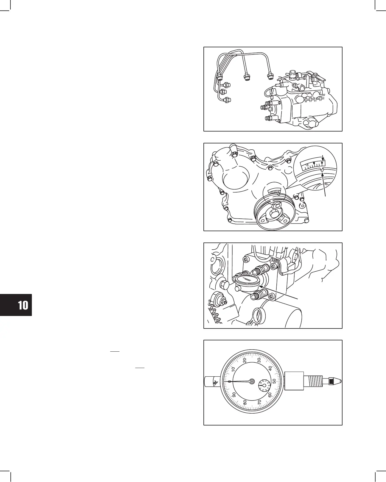
3. Remove distributor head screw with washer and
install injector pump timing gage,dial indicator Tool
# 19441, Fig. 3.
Fig. 3 – Install Timing Tool
TOOL #19441
DIAL INDICATOR
4. Slowly rotate crankshaft counter-clockwise until
dial indicator needle just stops moving. Set dial
indicator at ‘‘0,” Fig. 4.
NOTE: When indicator needle just stops moving,
carefully rock crankshaft clockwise slight-
ly, then counter-clockwise slightly to verify
absolute ‘‘0.”
Fig. 4 – Setting Indicator
 Loading...