6. Replacing Parts
6-2-5. Connectors
Any troubles can occur if connectors are not properly connected.
Before starting your troubleshooting, be sure that there is no contact failure between pins and wires, and that
all connectors have been properly inserted.
<Note>
Take care to avoid soiling the contacts (metallic surface) of the FFCs (Flexible Flat Cables) for Carriage
signals, Print Head Power Supply unit, Panels and
other parts with ink or grease.
Furthermore, avoid touching the FFC contacts with bare hands. Circuits may not function if FFC contacts are
soiled.
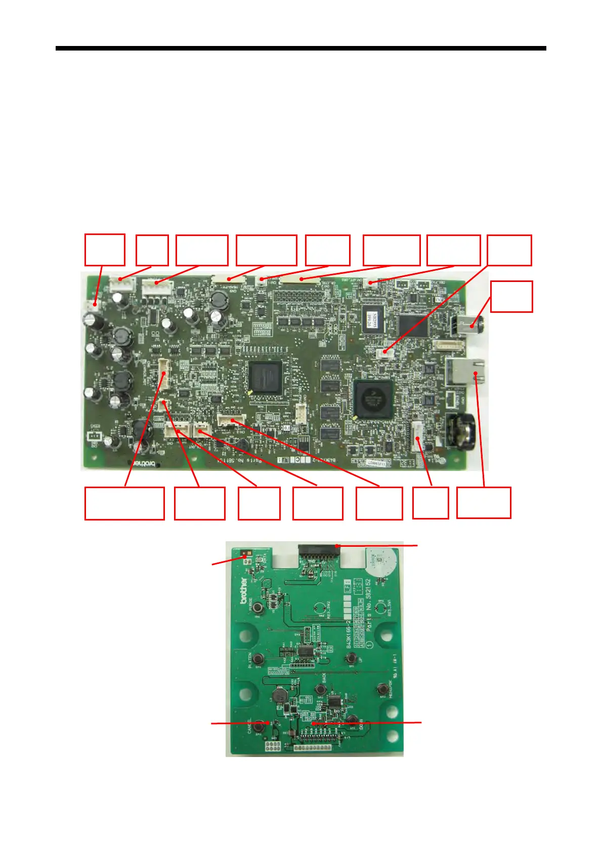
6-2-6. Connector Locations
Main PCB
GT-3 Series
314
Panel PCB
CN1
DC_IN
CN23
CN6
JAM&CR_MOT
CN10
H_MEN
CN8
EX_OUT
CN7
EX_IN
CN17
PNL
CN5
PNL_PW
CN2 PRINT SW (backside)
CN3 BACK LIGHT (backside)
CN3
MNT
CN4
PT
MOT
CN9
HEAD
PW
USB_F
CN22
ETHER_1
CN15
USB
H
CN11 CN12
CR
CTRL
CN14
PT
ORG SPEAK
CN4
CN1 MAIN (backside)
 Loading...