Contents
List of Figures
Figure 1 — Flushing Filter
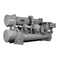
Figure 2 — 17MA, PA and SA Size 30 and 40 Compressors (Typical)
Figure 3 — Series 2500 Level Controller
Figure 4 — Typical Oil Pressure Switch
Figure 5 — Typical Load Limiting Control Assembly
Figure 6 — Demand Limit Controller
Figure 7 — Electro-Pneumatic Transducer
Figure 8 — Automatic Suction Damper
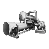
Figure 9 — Pumpout Unit (Typical Earlier Model 5F Unit)
Figure 10 — Pumpout Unit Piping, 5F Unit without Vent Valve or
Charging Connection (Earlier Model)
Figure 11 — Pumpout Unit Piping, 5F Unit with Vent Valve and
Charging Connection
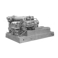
Figure 12 — 6D Pumpout Unit and Piping Schematic (Typical)
 Loading...