Manufacturer reserves the right to discontinue, or change at any time, specifications or designs without notice and without incurring obligations.
PC 903 Catalog No. 533-00030 Printed in U.S.A. Form 30G,R-2SI Pg 1 102 7-01 Replaces: 30G-25SI
Book 2
Ta b 5 c
Installation Instructions
Part No. 30GT-911---057
PACKAGE CONTENTS
NOTE: Mounting surface gasket must be reduced to half its original size to
prevent leakage. Because slight variations in accessory thickness may occur,
use appropriate combination of screws and washers for your installation.
SAFETY CONSIDERATIONS
Installation of this accessory can be hazardous due to elec-
trical components and equipment location (such as a roof, or
elevated structure). Only trained, qualified installers and
service mechanics should install and service this equipment.
When installing this accessory, observe precautions in the
literature, labels attached to the equipment, and other safety
precautions that apply.
• Follow all safety codes.
• Wear safety glasses and work gloves.
• Use care in handling and installing this accessory.
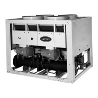
GENERAL
The accessory unit control display access door is designed
for all 30GTN015-420, 30GN,GT,GU,GTR,GUN,GUR040-
420, 30GX080-350, 30GXN,R080-528 and 30RA010-055
units. See Fig. 1. It provides easy access to the unit controls
module without having to open or remove unit panels.
NOTE: The 30GT,GN,GU,GTN,GTR,GUN,GUR230-420 and
30GXN,R 220, 240, 275, 300, 320, 345-528 (50 Hz), 370-528
(60 Hz) are modular units consisting of two smaller units joined
together. These modular unit sizes will require two accessory
packages.
INSTALLATION
Inspect package contents for missing or damaged parts. File
a claim with shipping agency if parts are damaged, and notify
your Carrier representative if any item is missing.
Inspect the mounting surface gasket on the accessory (see
Fig. 2) to be sure it is not cut or damaged, and that it is properly
installed in the seal groove of the window frame. If there is
damage, contact your local representative before proceeding. If
the gasket has slipped out of the seal groove, reinsert it before
proceeding.
Refer to Fig. 3-9 to find the correct location for the accesso-
ry for the appropriate unit. After locating the correct location
for installation, proceed as follows:
1. Remove control box door from the unit to prevent
damage to the control box components.
2. Secure template in the back of this book onto the control
box door where the accessory is to be mounted.
3. Using the mounting template in the back of this book, cut
out the area where the window is to be mounted.
4. Drill out screw locations with a no. 5 (.2055 in. [5.22 mm]
diameter) or no. 6 (.2040 in. [5.18 mm] diameter) drill.
5. File away any rough spots in the cutout area that may
cause personal injury or product damage.
ITEM QUANTITY
Hinged Window and Frame 1
No. 8,
7
/
8
-in. Screw 4
No. 8, 1
1
/
8
in. Screw 4
Washer 8
O-Ring 4
Cap Nut 4
ELECTRIC SHOCK HAZARD.
To avoid the possibility of electrical shock,
open and tag all remote disconnects before
installing this equipment.
DO NOT cut hole larger than template. If hole is larger
than template, water may leak into the unit and cause dam-
age to unit controls. Unit wiring schematics can also be
damaged if hole is cut too large.
30GN,GT,GU040-420
30GTR,GUN,GUR040-420
30GTN015-420, 30RA010-055
30GXN,R080-528
30GX080-350
Accessory Unit Control Display Access Door
50/60 Hz
Fig. 1 — Accessory Unit Display Access Door
*If necessary.
Fig. 2 — Accessory Installation
→