Owner’s Manual
Part Number 33CS071-01
CONTENTS
Page
GENERAL ...................................1
CONFIGURATION ...........................1,2
Thermostat Display ..........................1
Heat or Cool Indicator ........................1
Thermostat Front Panel Buttons ..............1
Thermostat Inner Panel Buttons ..............2
OPERATION .................................3
Mode ........................................3
Two-Stage Operation .........................3
Electric Heat .................................3
Dry Contact Switch/External Device ...........3
Remote Temperature Sensor ..................3
Outdoor Temperature Sensor .................3
IMPORTANT: Read entire instructions before configuring
the thermostat.
GENERAL
Carrier’s commercial, non-programmable thermostats are
wall-mounted, low-voltage thermostats which maintain room
temperature by controlling the operation of an HVAC (heat-
ing, cooling and ventilation) system. Separate heating and
cooling set points and auto-changeover capability allow flex-
ibility. Dry contacts are provided for optional wiring to field-
supplied external output device to control thermostat to oc-
cupied and unoccupied set points for energy savings.
Batteries are not required. During power interruption the
internal NEVERLOST™ memory stores thermostat con-
figuration for an unlimited time.
IMPORTANT: The thermostat has a configurable security
level. If certain functions are not available (such as chang-
ing set points), the thermostat security level may be
configured to exclude those functions. Call the installer to
reconfigure the security level.
CONFIGURATION
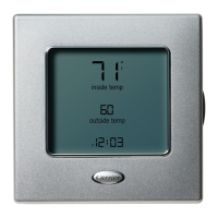
Thermostat Display —
The thermostat display is lo-
cated in the center of the thermostat. See Fig. 1. The fol-
lowing information can be displayed on the screen:
• mode (OFF, HEAT, COOL, or AUTO)
• fan setting (FAN ON or blank)
• override indication
• room temperature
• desired temperature
• service filter indicator
• outside temperature
• Occupied or Unoccupied mode (with dry contact connec-
tion to external device)
• setup indicator (configuration mode)
• lock indicator
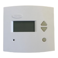
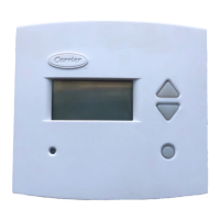
Heat or Cool Indicator — A Heat or Cool indicator is
located on the bottom left cover of the thermostat. See
Fig. 2. The light will be red if the thermostat is in Heating
mode. The light will be green if the thermostat is in Cooling
mode.
Thermostat Front Panel Buttons — The thermo-
stat has buttons on the front cover which are used to raise or
lower the desired set point and override the current program.
See Fig. 2.
SET POINT BUTTONS — The UP ARROW and DOWN
ARROW buttons will raise or lower the current desired tem-
perature set point. If the thermostat is inAUTO mode, press-
ing the UP ARROW or DOWN ARROW buttons will adjust
both the heating and cooling set points. Pressing the UP
ARROW or DOWN ARROW buttons in Cooling mode will
adjust only the cooling set points. Pressing the UP ARROW
or DOWNARROW buttons in Heating mode will adjust only
the heating set points. The UP ARROW and DOWN
ARROW buttons are also used in programming mode.
Fig. 1 — Thermostat Display
33CS
Commercial Non-Programmable
Thermostat
Manufacturer reserves the right to discontinue, or change at any time, specifications or designs without notice and without incurring obligations.
Book 1 4
Tab 11a 13a
PC 111 Catalog No. 533-331 Printed in U.S.A. Form 33CS-5SO Pg 1 1-98 Replaces: New