Installation, Start-Up, and
Operating Instructions
Part Number 33CSPTN-01
CONTENTS
Page
SAFETY CONSIDERATIONS ...................1
GENERAL ...................................1
INSTALLATION .............................1-10
Step 1 — Thermostat Location ................1
Step 2 — Set DIP Switches ...................1
Step 3 — Install Thermostat ..................2
Step 4 — Space Temperature Averaging .......2
Step 5 — Set Thermostat Configuration .......2
Step 6 — Check Thermostat Operation ........9
Step 7 — Select Thermostat Operation
Settings ....................................9
Step 8 — Set Current Time ...................9
Step 9 — Set Current Day ....................9
Step 10 — Programming Thermostat
Schedules .................................10
Step 11 — Final Checklist ...................10
OPERATION ...............................11,12
Hold, Fan, and Mode Botton Operation .......11
Thermostat Output Assignments .............11
Five-Minute Compressor Short-Cycle
Protection .................................11
Fifteen-Minute Staging Timer ................11
Two-Minute Minimum On Time ...............11
Heating (Cooling Set Point Minimum
Difference) .................................11
Auto-Changeover Timer .....................11
Power-On Thermostat Check ................11
Error Codes ................................11
Smart Recovery (Heating Mode Only) ........12
TROUBLESHOOTING ........................12
IMPORTANT: Read entire instructions before starting
the installation.
SAFETY CONSIDERATIONS
Read and follow manufacturer instructions carefully. Fol-
low all local electrical codes during installation. All wiring
must conform to local and national electrical codes. Im-
proper wiring or installation may damage thermostat.
Recognize safety information. This is the safety alert sym-
bol
. When the safety alert symbol is present on equip-
ment or in the instruction manual, be alert to the potential
for personal injury.
Understand the signal words DANGER, WARNING, and
CAUTION. These words are used with the safety alert sym-
bol. DANGER identifies the most serious hazards which will
result in severe personal injury or death. WARNING signi-
fies a hazard which could result in personal injury or death.
CAUTION is used to identify unsafe practices which would
result in minor personal injury or property damage.
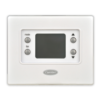
GENERAL
Carrier’s 7-day, commercial, programmable thermostats
are wall-mounted, low-voltage thermostats which maintain
room temperature by controlling the operation of an HVAC
(heating, cooling and ventilation) system. Separate heating
and cooling set points and auto-changeover capability allow
occupied and unoccupied programming for energy savings.
All thermostats allow up to 4 time/temperature settings to
be programmed per 24-hr period. Each thermostat stores pro-
grams for 7 independent days. Batteries are not required. Dur-
ing power interruption the internal memory stores comfort
schedules for an unlimited time while the clock continues to
run for at least 72 hours.
The thermostat can be configured to accept several dif-
ferent equipment configurations, from single-stage heat-
ing and cooling to 3 stages of heating (heat pump only) and
2 stages of cooling. The thermostat comes factory config-
ured for one stage of cooling and one stage of heating.
INSTALLATION
Step 1 — Thermostat Location —
The thermostat
should be mounted:
• approximately 5 ft from the floor
• close to or in a frequently used room, preferably on an
inside partitioning wall
• on a section of wall without pipes or ductwork
The thermostat should not be mounted:
• close to a window, on an outside wall, or next to a door
leading to the outside
• where exposed to direct light and heat from a lamp, the
sun, a fireplace, or any other temperature-radiating object
which may cause a false reading
• close to or in direct airflow from supply registers or return
air grilles
• in areas with poor air circulation (such as behind a door or
in an alcove)
• where temperature operating limits are within 41 to 104 F
(5 to 40 C)
• where humidity operating range is within 0 to 95% rela-
tive humidity, non-condensing
Step 2 — Set DIP Switches — There are 4 small
DIP (Dual In-line Package) switches on the back of the cir-
cuit board which must be configured by the installer. The
ON position is indicated by small letters on the switch. Ig-
nore the numbers (1-4) on the switch. The switch designa-
tion (A-D) is printed on a sticker next to the switch. To change
a switch position, use the corner of a small screwdriver to
slide the switch ON or OFF. Set the DIP switches before
installing the thermostat.
33CS
Commercial Thermostat
Manufacturer reserves the right to discontinue, or change at any time, specifications or designs without notice and without incurring obligations.
Book 1 4
Tab 11a 13a
PC 111 Catalog No. 533-313 Printed in U.S.A. Form 33CS-8SI Pg 1 4-97 Replaces: 33CS-6SI