35
Table 9 — Economizer Module - Right Hand Terminal
Blocks
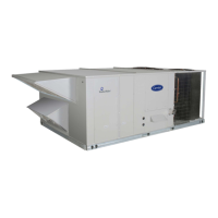
Fig. 48 — S-Bus Sensor DIP Switches
Use Fig. 48 and Table 10 to locate the wiring terminals for each
enthalpy control sensor.
Table 10 — HH57AC081 Sensor Wiring Terminations
Use Fig. 48 and Table 11 to set the DIP switches for the desired
use of the sensor.
Table 11 — HH57AC081 Sensor DIP Switch
NOTE: When a S-bus sensor is connected to an existing network,
it will take 60 minutes for the network to recognize and auto-con-
figure itself to use the new sensor.
During the 60 minute setup period, no alarms for sensor failures
(except SAT) will be issued and no economizing function will be
available.
CO
2
SENSOR WIRING
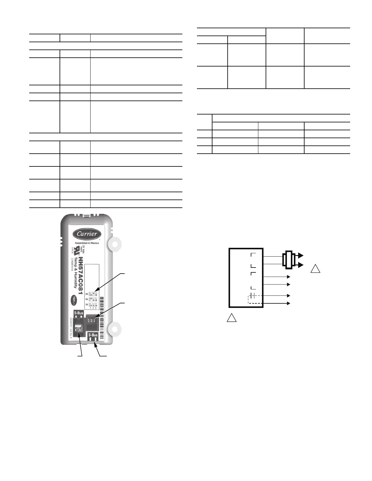
When using a CO
2
sensor, the black and brown common wires are
internally connected and only one is connected to “IAQ COM” on
the W7220. Use the power from the W7220 to power the CO
2
sensor OR make sure the ground for the power supplies are com-
mon. See Fig. 49 for CO
2
sensor wiring.
Fig. 49 — CO
2
Sensor Wiring
INTERFACE OVERVIEW
This section describes how to use the economizer’s user interface
for:
• Keypad and menu navigation
• Settings and parameter changes
• Menu structure and selection
USER INTERFACE
The user interface consists of a 2-line LCD display and a 4-button
keypad on the front of the economizer controller.
KEYPAD
The four navigation buttons (see Fig. 50) are used to scroll
through the menus and menu items, select menu items, and to
change parameter and configuration settings.
LABEL TYPE DESCRIPTION
Top Right Terminal Blocks
AUX2 I 24 vac IN The first terminal is not used.
OCC 24 vac IN
Shut Down (SD) or HEAT (W)
Conventional only
and
Heat Pump Changeover (O-B) in Heat
Pump mode.
E-GND E-GND Occupied/Unoccupied Input
EXH1 24 vac OUT Exhaust Fan 1 Output
AUX1 O 24 vac OUT
Programmable:
Exhaust fan 2 output
or
ERV
or
System alarm output
Bottom Right Terminal Blocks
Y2-I 24 vac IN
Y2 in - Cooling Stage 2 Input from space
thermostat
Y2-O 24 vac OUT
Y2 out - Cooling Stage 2 Output to stage
2 mechanical cooling
Y1-I 24 vac IN
Y1 in - Cooling Stage 2 Input from space
thermostat
Y1-O 24 vac OUT
Y1 out - Cooling Stage 2 Output to stage
2 mechanical cooling
C COM 24 vac Common
R 24 vac 24 vac Power (hot)
DIP
SWITCH
LABEL
DIP
SWITCHES
(3)
S-BUS
2 PIN SIDE
CONNECTOR
S-BUS
TERMINALS
(1 AND 2)
TERMINAL
TYPE DESCRIPTION
NUMBER LABEL
1 S-BUS S-BUS
S-BUS
Communications
(Enthalpy Control
Sensor Bus)
2 S-BUS S-BUS
S-BUS
Communications
(Enthalpy Control
Sensor Bus)
USE
DIP SWITCH POSITIONS FOR SWITCHES 1, 2, AND 3
123
DA OFF ON OFF
RA ON OFF OFF
OA OFF OFF OFF
CO
2
SENSOR
24V
ANALOG
OUT
L1
(HOT)
L2
RED
BLACK
YELLOW
BROWN
ORANGE
GREEN
+
–
POWER SUPPLY. PROVIDE DISCONNECT
MEANS AND OVERLOAD PROTECTION
AS REQUIRED.
1
1
 Loading...