Installation, Start-Up, and
Service Instructions
CONTENTS
Page
SAFETY CONSIDERATIONS ...................1
INSTALLATION .............................1-26
Step 1 — Provide Unit Support ...............1
• ROOF CURB
• SLAB MOUNT
Step 2 — Field Fabricate Ductwork ............2
Step 3 — Install External Trap for
Condensate Drain ..........................2
Step 4 — Rig and Place Unit ..................2
• POSITIONING
Step 5 — Install Flue Hood ...................4
Step 6 — Install Gas Piping ...................4
Step 7 — Make Electrical Connections ........4
• DISCONNECT BOX LOCATION
• FIELD POWER SUPPLY
• FIELD CONTROL WIRING
• HEAT ANTICIPATOR SETTINGS
Step 8 — Make Outdoor-Air Adjustments and
Install Outdoor-Air Hood ..................13
• MANUAL OUTDOOR-AIR DAMPER
• OPTIONAL VARISLIDE™ ECONOMIZER
• OPTIONAL PARABLADE ECONOMIZER
Step 9 — Adjust Evaporator-Fan Speed ......18
• DIRECT DRIVE MOTORS
• BELT DRIVE MOTORS
START-UP .................................27,28
SERVICE ..................................29-33
TROUBLESHOOTING ......................34-40
START-UP CHECKLIST .....................CL-1
SAFETY CONSIDERATIONS
Installation and servicing of air-conditioning equipment
can be hazardous due to system pressure and electrical com-
ponents. Only trained and qualified service personnel should
install, repair, or service air-conditioning equipment.
Untrained personnel can perform basic maintenance func-
tions of cleaning coils and filters and replacing filters. All
other operations should be performed by trained service per-
sonnel. When working on air-conditioning equipment, ob-
serve precautions in the literature, tags and labels attached
to the unit, and other safety precautions that apply.
Follow all safety codes. Wear safety glasses and work gloves.
Use quenching cloth for unbrazing operations. Have fire ex-
tinguishers available for all brazing operations.
Disconnect gas piping from unit when leak
testing at pressure greater than
1
⁄
2
psig.
Pressures greater than
1
⁄
2
psig will cause
gas valve damage resulting in hazardous
condition. If gas valve is subjected to pres-
sure greater than
1
⁄
2
psig, it must be re-
placed before use. When pressure testing
field-supplied gas piping at pressures of
1
⁄
2
psig or less, a unit connected to such
piping must be isolated by manually clos-
ing the gas valve.
Before performing service or maintenance operations on
unit, turn off main power switch to unit. Electrical shock
could cause personal injury.
INSTALLATION
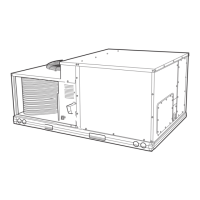
Unit is shipped in the vertical discharge configuration. To
convert to horizontal configuration, remove screws from side
duct opening covers and remove covers. Using the same screws,
install covers on vertical duct openings with the insulation-
side down. Seals around duct openings must be tight. See
Fig. 1.
Step 1 — Provide Unit Support
ROOF CURB — Assemble and install accessory roof curb
in accordance with instructions shipped with curb. See
Fig. 2. Install insulation, cant strips, roofing felt, and counter
flashing as shown. Ductwork must be attached to curb, not
to the unit. The accessory thru-the-bottom power connection
package must be installed before the unit is set on the roof
curb. If field installed (through the roof curb) gas connec-
tions are desired, use factory supplied
3
⁄
4
in. pipe coupling
and gas plate assembly to mount the through the roof curb
connection to the roof curb. Gas connections and power con-
nections to the unit must be field installed after the unit is
installed on the roof curb.
IMPORTANT: The gasketing of the unit to the roof
curb is critical for a watertight seal. Install gasket sup-
plied with the roof curb as shown in Fig. 2. Improp-
erly applied gasket can result in air leaks and poor unit
performance.
48TJE/TJF004
48TJD/TJE/TJF005-007
Single-Package Rooftop Heating/Cooling Units
Manufacturer reserves the right to discontinue, or change at any time, specifications or designs without notice and without incurring obligations.
Book 1 4
Tab 1a 6a
PC 111 Catalog No. 534-852 Printed in U.S.A. Form 48TJ-9SI Pg 1 8-95 Replaces: 48TJ-3SI