4
Removing the Return Air Filters
1. Remove the return air filter and indoor coil access
panel. See Fig. 1.
2. Reach inside and remove filters from the filter rack.
3. Replace these filters as required with similar replace-
ment filters of same size.
4. Re−install the return air filter and indoor coil access
panel.
Outdoor Air Hood
Outside air hood inlet screens are permanent
aluminum−mesh type filters. See Fig. 2. Inspect these
screens for cleanliness. Remove the screens when
cleaning is required. Clean by washing with hot
low−pressure water and soft detergent and replace all
screens before restarting the unit. Observe the flow
direction arrows on the side of each filter frame.
Economizer Inlet Air Screen
This air screen is retained by spring clips under the top
edge of the hood. (See Fig. 3.)
CLEANABLE
ALUMINUM
SCREEN
HOOD
FILTER
CLIP
OUTSIDE
AIR
BAROMETRIC
RELIEF
DIVIDER
17 1/4
(438 mm)
C06027
Fig. 3 − Inlet Air Screen Installation
Remove screens be removing the screws in the horizontal
clips on the leading edge of the hood. Slide the filters out.
See Fig. 3.
Install the filters by sliding clean or new filters into the
hood side retainers. Once positioned, re−install the
horizontal clips.
SUPPLY FAN (BLOWER) SECTION
ELECTRICAL SHOCK HAZARD
Failure to follow this warning could cause personal
injury or death.
Before performing service or maintenance operations
on the fan system, shut off all unit power and
Lockout/Tagout the unit disconnect switch. DO NOT
reach into the fan section with power still applied to
the unit.
!
WARNING
Supply Fan Assembly
The supply fan system consists of two forward−curved
centrifugal blower wheels mounted on a solid blower shaft
that is supported by two greasable pillow block concentric
bearings. A fixed−pitch driven fan pulley is attached to
the fan shaft and an adjustable−pitch driver pulley is
mounted on the motor. The pulleys are connected using a
V−belt. (See Fig. 4.)
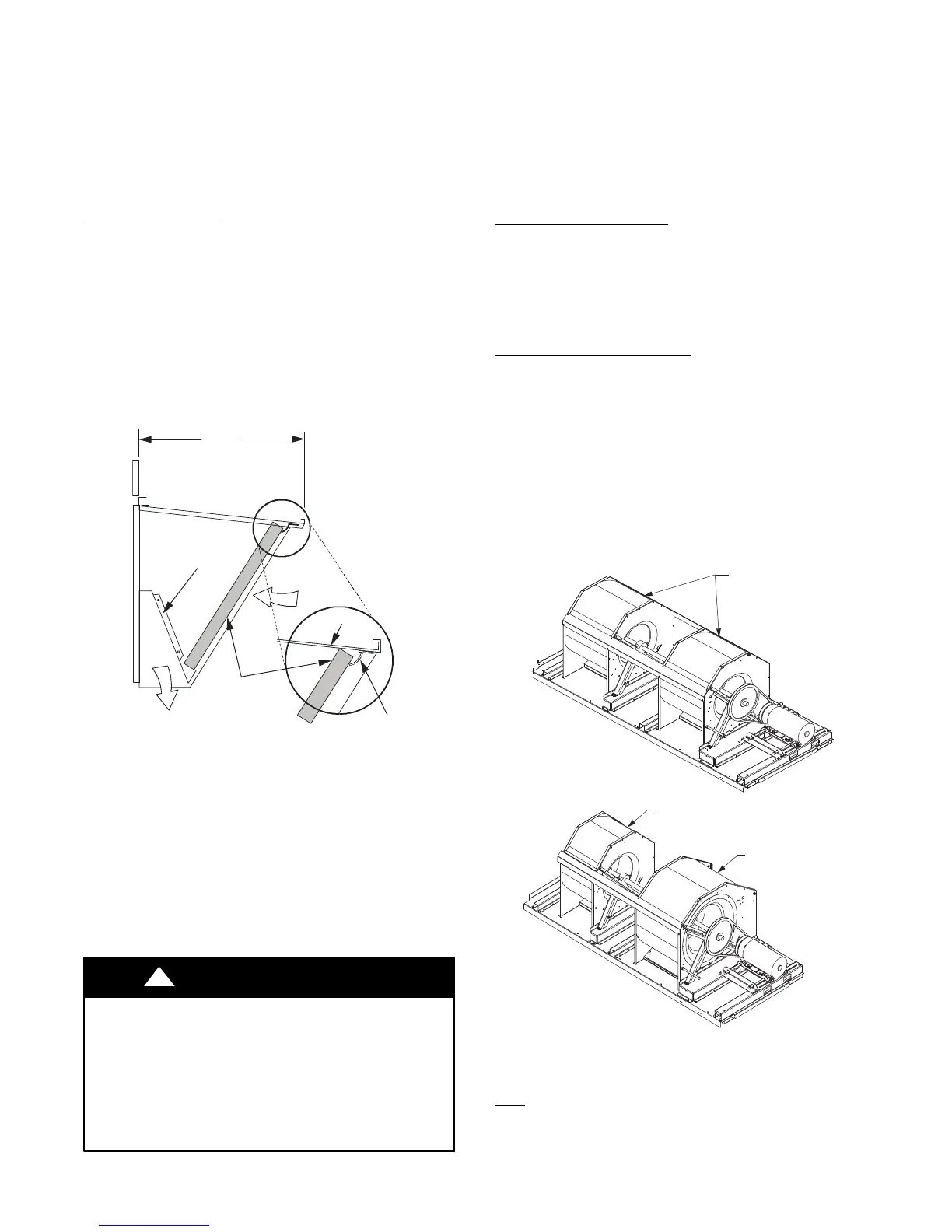
Vertical Supply Models
The two fan wheels used on the vertical supply models are
the same: 15″ diameter x 15″ width. This arrangement
provides uniform airflow distribution across the width of
the evaporator coil, electric heater, and into the supply
duct.
Horizontal Supply Models
The horizontal supply models have two different fan
wheel sizes on a single shaft. The front side wheel is 18″
diameter x 15″ wide, while the rear side fan is 15″
diameter x 11″ wide. This arrangement promotes uniform
airflow across the width of the evaporator coil and heater
assembly while using a supply outlet on the rear side of
the unit.
NOTE: This major difference in the fan system design
makes it impossible to field−convert the 50TC unit’s
supply fan outlet configuration.
VERTICAL SUPPLY FANS
HORIZONTAL SUPPLY FANS
15” X 15” SUPPLY FANS
15” X 11” SUPPLY FAN
18” X 15” SUPPLY FAN
C12683
Fig. 4 − Supply Fan Arrangements
Belt
Check the belt condition and tension quarterly. Inspect the
belt for signs of cracking, fraying or glazing along the
inside surfaces. Check belt tension by using a spring−force
 Loading...


