Installation Instructions
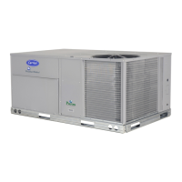
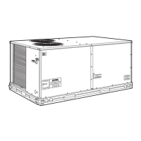
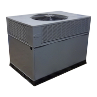
50TCQ14
Single Package Rooftop
Heat Pump
with Puronr (R---410A) Refrigerant
Size 14
50TCQ units for installation in the United States contain use of Carrier's Staged Air Volume
(SAV™) 2-speed indoor fan control system. This complies with the U.S. Department of
Energy (DOE) efficiency standard of 2018.
50TCQ units for installation outside the United States may or may not contain use of the SAV
2-speed indoor fan control system as they are not required to comply with the U.S.
Department of Energy (DOE) efficiency standard of 2018.
For specific details on operation of the Carrier SAV 2-speed indoor fan system refer to the
Variable Frequency Drive (VFD) Factory-Installed Option 2-Speed Motor Control Installation,
Setup and Troubleshooting manual.
NOTE: Read the entire instruction manual before starting
the installation.
TABLE OF CONTENTS
SAFETY CONSIDERATIONS 3....................
Rated Indoor Airflow (cfm) 4.....................
REFRIGERATION SYSTEM COMPONENTS 7.......
INSTALLATION 9...............................
Jobsite Survey 9................................
Step 1 -- Plan for Unit Location 9..................
Roof Mount 9...............................
Step 2 -- Plan for Sequence of Unit Installation 9......
Curb--mounted Installation 9...................
Pad--mounted Installation 9....................
Frame--mounted Installation 9..................
Step 3 -- Inspect Unit 9...........................
Step 4 -- Provide Unit Support 9...................
Roof Curb Mount 9..........................
Slab Mount (Horizont al Units Only) 11..........
Alternate Unit Support
(In Lie u of Curb or Slab Mount) 11.............
Step 5 -- Field Fabricate Ductwork 11...............
For Units with Accessory Electric Heaters 11.....
Step 6 -- Rig and Place Unit 11....................
Positioning on Curb 11.......................
Step 7 -- Convert to Horizontal and Connect
Ductwork 12...........................
Step 8 -- Install Outside Air Hood 12...............
Economizer Hood Removal and Setup --
Factory Option 12...........................
Two Position Damper Hood Removal and Setup --
Factory Option 12...........................
Economizer Hood and Two--Position Hood 13.....
Step 9 -- Install External Condensate Trap
and Line 14............................
Step 10 -- Make E lectrical Connections 15...........
Field Power Supply 15........................
All Units 16................................
Units Without Factory--Installed
Non--Fused Disconnect 19.....................
Units with Factory--Installed
Non--Fused Disconnect 19.....................
Convenie nce Outlets 19.......................
Factory--Option Thru--Base Connections 21.......
Units Without Thru --Base Connections 21........
Field Control Wiring 21.......................
Thermostat 21...............................
Central Terminal Board 22......................
Commercial Defrost Control 22..................
Unit Without Thru--Base Conversion Kit 24.......
Heat Anticipator Settings 24...................
Electric Heaters 24............................
Single Point Boxes 25........................
Heate r and Supplementary Fuses 25.............
Heate r Low--Voltage Control Connections 25......