7
1/
2
OD
INDUCER HOUSING
DRAIN CONNECTION
1/
4
OD
COLLECTOR BOX TO
TRAP RELIEF PORT
5/
8
OD
COLLECTOR BOX
DRAIN CONNECTION
1/
2
-IN. PVC OR CPVC
SCREW HOLE FOR
UPFLOW APPLICATIONS
(OPTIONAL)
1
4
2
7
8
1
8
7
WIRE TIE
GUIDES
(WHEN USED)
1
2
1
3
4
1
3
4
FRONT VIEW SIDE VIEW
FURNACE
DOOR
CONDENSATE
TRAP
7
8
1
4
26
4
FURNACE
SIDE
1
2
1
SIDE VIEW FRONT VIEW
FIELD
DRAIN
CONN
CONDENSATE
TRAP (INSIDE)
BLOWER SHELF
ALTERNATE DRAIN
TUBE LOCATION
CONDENSATE TRAP
DRAIN TUBE LOCATION
FACTORY-SHIPPED LOCATION
ALTERNATE LOCATION
A06501
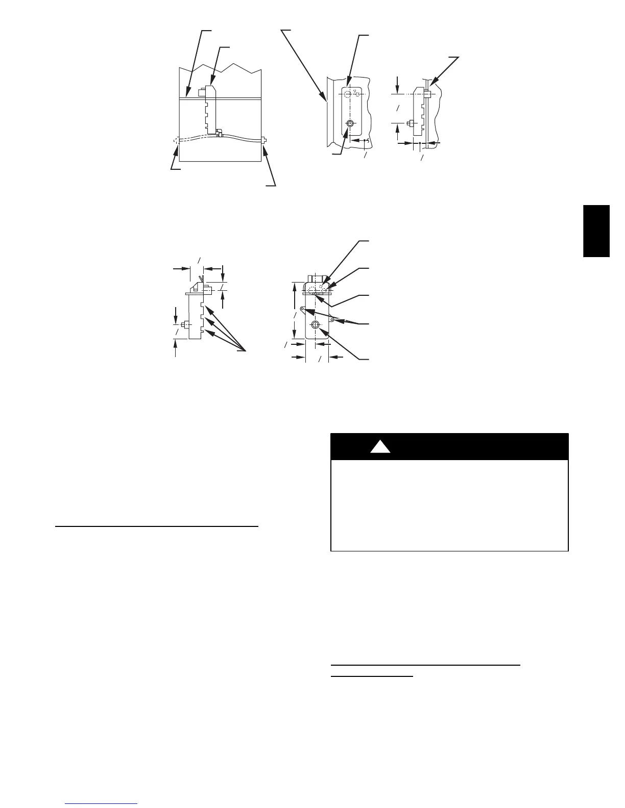
Fig. 6 --- Condensate Trap
NOTE: Failure to use CPVC elbows may allow drain to kink,
preventing draining.
f. Connect lar ger diameter drain tube and clamp
(factory--supplied in loose parts bag) to condensate
trap and clamp securely.
g. Route tube to coupling and cut to appropriate length.
h. Attach tube to coupling and clamp securely .
CONDENSATE TRAP(ALTERNATE LOCA
TION)
An alternate location for the condensate trap is the left--hand side
of casing. (See Fig. 2 and 8.)
NOTE: If the alternate left--hand side of casing location is used,
the factory -- connected drain and relief port tubes must be
disconnected and modified for attachment. See Condensate Trap
Tubing (Alternate Configuration) section for tubing attachment.
To relocate condensate trap to the left-- hand side, perform the
following:
1. Remove 3 tubes connected to condensate trap.
2. Remove trap from blower shelf by gently pushing tabs
inward and rotating trap.
3. Install casing hole filler cap (factory--supplied in loose
parts bag) into blower shelf hole where trap was removed.
CARBON MONOXIDE POISONING HAZARD
Failure to follow this warning could result in personal
injury or death.
Casing hole filler cap must be installed in blower shelf
hole when condensate trap is relocated to prevent
combustion products being drawn in from appliances in
the equipment room.
!
WARNING
4. Install condensate trap into left--hand casing hole by
inserting the top two outer tabs into casing hole, while
making sure that the larger center tab is on the outside of
the casing. Push the condensate trap up as far as possible
and then rotate the connection stubs through the hole.
Slide the condensate trap downwards to secure it in the
casing hole.
5. Fill unused condensate trap casing holes with plastic filler
caps (factory--supplied in loose parts bag).
CONDENSATE TRAP TUBING (ALTERNA
TE
CONFIGURA
TION)
NOTE: See Fig. 8 or tube routing label on main furnace door to
confirm location of these tubes.
1. Collector Box Drain Tube
Connect collector box drain tube (blue label) to
condensate trap.
NOTE: On 17--1/2--in. wide furnaces ONLY, cut tube between
corrugated sections to prevent kinks.
58UVB
 Loading...