Manufacturer reserves the right to discontinue, or change at any time, specifications or designs without notice and without incurring obligations.
Catalog No. 04-53420027-01 Printed in U.S.A. Form 42WKN-11SI Pg 1 11-23 Replaces: 42WKN-10SI
Installation, Operation and Maintenance
Instructions
CONTENTS
Page
SAFETY CONSIDERATIONS . . . . . . . . . . . . . . . . . . . 1
SPECIAL PRECAUTIONS . . . . . . . . . . . . . . . . . . . . . . 2
Special Precautions . . . . . . . . . . . . . . . . . . . . . . . . . . 2
Précautions Particulières . . . . . . . . . . . . . . . . . . . . . . 2
Hazard Intensity Levels . . . . . . . . . . . . . . . . . . . . . . . 2
Hiérarchie Des Niveaux De Risques . . . . . . . . . . . . . 2
INSPECTION . . . . . . . . . . . . . . . . . . . . . . . . . . . . . . . . 4
CONTROLS DESCRIPTION . . . . . . . . . . . . . . . . . . . . 10
Microprocessor Control Board . . . . . . . . . . . . . . . . 10
Inputs . . . . . . . . . . . . . . . . . . . . . . . . . . . . . . . . . . . . . 10
Outputs . . . . . . . . . . . . . . . . . . . . . . . . . . . . . . . . . . . 10
• INDOOR FAN MOTOR
• CONDENSATE PUMP
• VANE MOTOR
• ELECTRIC HEAT
External Connections . . . . . . . . . . . . . . . . . . . . . . . . 10
Microprocessor PCB Battery (P/N CR2032) . . . . . . 10
Controller . . . . . . . . . . . . . . . . . . . . . . . . . . . . . . . . . . 10
Infrared Receiver . . . . . . . . . . . . . . . . . . . . . . . . . . . . 10
Self Diagnostics . . . . . . . . . . . . . . . . . . . . . . . . . . . . 10
Receiver Indicators . . . . . . . . . . . . . . . . . . . . . . . . . . 10
PRE-INSTALLATION . . . . . . . . . . . . . . . . . . . . . . . . . 42
Unpack Unit . . . . . . . . . . . . . . . . . . . . . . . . . . . . . . . . 42
Blank Off Pieces . . . . . . . . . . . . . . . . . . . . . . . . . . . . 42
Positioning . . . . . . . . . . . . . . . . . . . . . . . . . . . . . . . . . 42
Ceiling Opening Sizes . . . . . . . . . . . . . . . . . . . . . . . 42
Positioning the Electro-Mechanical Thermostat . . 42
INSTALLATION . . . . . . . . . . . . . . . . . . . . . . . . . . . . . 42
Step 1 — Hanger Bolts . . . . . . . . . . . . . . . . . . . . . . . 42
Step 2 — Installation Guide . . . . . . . . . . . . . . . . . . . 43
• INSTALLATION GUIDE SETUP
Step 3 — Condensate Piping . . . . . . . . . . . . . . . . . . 43
Step 4 — Duct Collars . . . . . . . . . . . . . . . . . . . . . . . . 43
• DUCT COLLARS
• SUPPLY AIR DUCT COLLARS
• OUTSIDE AIR DUCT COLLARS
• INSTALLING OUTSIDE AND/OR SUPPLY AIR DUCT
COLLARS
Step 5 — Piping Installation . . . . . . . . . . . . . . . . . . . 44
• PIPING INSULATION
Step 6 — Wiring . . . . . . . . . . . . . . . . . . . . . . . . . . . . . 45
TERMINAL STRIP CONNECTIONS
INSTALLATION . . . . . . . . . . . . . . . . . . . . . . . . . . . 46
Disconnect Switch . . . . . . . . . . . . . . . . . . . . . . . . . . 46
Step 7 — Fascia Assembly . . . . . . . . . . . . . . . . . . . 53
PRE-START-UP . . . . . . . . . . . . . . . . . . . . . . . . . . . . .53
Pre-Start Checks . . . . . . . . . . . . . . . . . . . . . . . . . . . .53
Control Circuit Checks . . . . . . . . . . . . . . . . . . . . . . .53
Sequence of Operation . . . . . . . . . . . . . . . . . . . . . . .55
• ELECTRO-MECHANICAL CONTROLS
• MICROPROCESSOR CONTROLS
OPERATION . . . . . . . . . . . . . . . . . . . . . . . . . . . . . . . .55
On/Off . . . . . . . . . . . . . . . . . . . . . . . . . . . . . . . . . . . . .55
Fan Speeds . . . . . . . . . . . . . . . . . . . . . . . . . . . . . . . .55
Modes . . . . . . . . . . . . . . . . . . . . . . . . . . . . . . . . . . . . .55
Temperature Setpoint . . . . . . . . . . . . . . . . . . . . . . . .55
Clock . . . . . . . . . . . . . . . . . . . . . . . . . . . . . . . . . . . . . .55
Timer . . . . . . . . . . . . . . . . . . . . . . . . . . . . . . . . . . . . . .55
Battery Replacement . . . . . . . . . . . . . . . . . . . . . . . . .55
CONTROLS . . . . . . . . . . . . . . . . . . . . . . . . . . . . . . . . .56
Setting Jumper Links . . . . . . . . . . . . . . . . . . . . . . . .56
Main Control Functions . . . . . . . . . . . . . . . . . . . . . . .56
• INDOOR FAN OPERATION
• TEMPERATURE CONTROL
• POWER FAILURE
Alarms . . . . . . . . . . . . . . . . . . . . . . . . . . . . . . . . . . . . .56
MAINTENANCE . . . . . . . . . . . . . . . . . . . . . . . . . . . . .56
Maintenance Schedule . . . . . . . . . . . . . . . . . . . . . . .57
• EVERY 3 MONTHS
• EVERY 6 MONTHS
• EVERY 12 MONTHS
Filter Removal and Cleaning . . . . . . . . . . . . . . . . . .57
Recommended Spares . . . . . . . . . . . . . . . . . . . . . . .57
DISASSEMBLY PROCEDURE . . . . . . . . . . . . . . . . . .57
Fan Removal . . . . . . . . . . . . . . . . . . . . . . . . . . . . . . .57
Condensate Tray Removal . . . . . . . . . . . . . . . . . . . .57
Condensate Pump Removal . . . . . . . . . . . . . . . . . . .58
TROUBLESHOOTING . . . . . . . . . . . . . . . . . . . . . . . .58
REPLACEMENT PARTS . . . . . . . . . . . . . . . . . . . . . .61
SAFETY CONSIDERATIONS
Installing and servicing air-conditioning equipment can be hazard-
ous due to system pressure and electrical components. Only
trained and qualified service personnel should install and service
air-conditioning equipment. See Fig. 1 for Proposition 65 warning
label. To assist in installation see Table 1 for conversion factors.
Untrained personnel can perform basic maintenance such as
cleaning and replacing filters. All other operations should be per-
formed by trained service personnel. When working on air-
conditioning equipment, observe safety precautions in literature
and on tags and labels attached to the unit.
1. The equipment has been designed and manufactured to
meet international safety standards but, like any mechani-
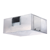
AirStream
™
42WKN08-36
Hydronic Ceiling Cassettes