Manufacturer reserves the right to discontinue, or change at any time, specifications or designs without notice and without incurring obligations.
Catalog No. 04-53300198-01 Printed in U.S.A. Form 30XV-7SI Pg 1 1-19 Replaces: 30XV-6SI
Installation Instructions
CONTENTS
Page
SAFETY CONSIDERATIONS. . . . . . . . . . . . . . . . . . . . . . 1
INTRODUCTION . . . . . . . . . . . . . . . . . . . . . . . . . . . . . . . . . . 3
INSTALLATION . . . . . . . . . . . . . . . . . . . . . . . . . . . . . . . . . . 3
Storage . . . . . . . . . . . . . . . . . . . . . . . . . . . . . . . . . . . . . . . . . . 3
Step 1 — Inspect Shipment . . . . . . . . . . . . . . . . . . . . . . 3
Step 2 — Place, Mount and Rig the Unit . . . . . . . . . 3
•PLACING UNIT
• MOUNTING UNIT
• EXPORT SHIPPING RAILS
• RIGGING UNIT
Step 3 — Make Refrigerant, Evaporator Fluid
and Drain Piping Connections . . . . . . . . . . . . . . . . 90
• SPLIT UNIT ASSEMBLY
• GENERAL
• EVAPORATOR PUMP CONTROL
• PREPARATION FOR YEAR-ROUND OPERATION
Step 4 — Fill the Chilled Water Loop . . . . . . . . . . . 100
• WATER SYSTEM CLEANING
• WATER TREATMENT
• SYSTEM PRESSURIZATION
• FILLING THE SYSTEM
• SET WATER FLOW RATE
• FREEZE PROTECTION
• PREPARATION FOR WINTER SHUTDOWN
Step 5 — Make Electrical Connections . . . . . . . . . 102
• POWER SUPPLY
• FIELD POWER CONNECTIONS
•POWER WIRING
• FIELD CONTROL POWER CONNECTIONS
• CARRIER COMFORT NETWORK
®
COMMUNICATION BUS WIRING
• BACNET IP OR ETHERNET COMMUNICATION
• NON-CCN COMMUNICATION WIRING
• FIELD CONTROL OPTION WIRING
• DUAL CHILLER LEAVING WATER SENSOR
Step 6 — Install Accessories . . . . . . . . . . . . . . . . . . . 127
• ENERGY MANAGEMENT MODULE
• UNIT SECURITY/PROTECTION ACCESSORIES
• COMMUNICATION ACCESSORIES
• SERVICE OPTIONS
Step 7 — Leak Test Unit. . . . . . . . . . . . . . . . . . . . . . . . 127
• DEHYDRATION
• REFRIGERANT CHARGE
SAFETY CONSIDERATIONS
Installation and servicing of air-conditioning equipment can be
hazardous due to system pressure and electrical components.
Only trained and qualified service personnel should install,
repair, or service air-conditioning equipment.
Untrained personnel can perform basic maintenance functions
of cleaning coils and filters and replacing filters. All other
operations should be performed by trained service personnel.
When working on air-conditioning equipment, observe precau-
tions in the literature, tags and labels attached to the unit,
and other safety precautions that may apply.
Follow all safety codes. Wear safety glasses and work gloves.
Use quenching cloth for unbrazing operations. Have fire extin-
guisher available for all brazing operations.
WARNING
Electrical shock can cause personal injury and death. Shut
off all power to this equipment during installation and ser-
vice. There may be more than one disconnect switch. Tag
all disconnect locations to alert others not to restore power
until work is completed.
WARNING
Electrical shock can cause personal injury and death. After
unit power is disconnected, wait at least 20 minutes for the
VFD (variable frequency drive) capacitors to discharge
before opening drive.
WARNING
DO NOT VENT refrigerant relief valves within a building.
Outlet from relief valves must be vented in accordance
with the latest edition of ANSI/ASHRAE (American
National Standards Institute/American Society of Heating,
Refrigerating and Air-Conditioning Engineers) 15 (Safety
Code for Mechanical Refrigeration). The accumulation of
refrigerant in an enclosed space can displace oxygen and
cause asphyxiation. Provide adequate ventilation in
enclosed or low overhead areas. Inhalation of high concen-
trations of vapor is harmful and may cause heart irregulari-
ties, unconsciousness or death. Misuse can be fatal. Vapor
is heavier than air and reduces the amount of oxygen avail-
able for breathing. Product causes eye and skin irritation.
Decomposition products are hazardous.
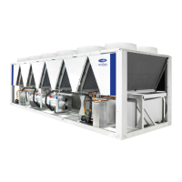
AquaForce
®
30XV140-500
Variable Speed Air-Cooled Liquid Chillers
with Greenspeed
®
Intelligence