Installation, Start–Up, Operating and
Service and Maintenance Instructions
SAFETY CONSIDERATIONS . . . . . . . . . . . . . . . . . . . . . . . . . . . . . . . 3
INTRODUCTION . . . . . . . . . . . . . . . . . . . . . . . . . . . . . . . . . . . . . . . . . 4
CODES AND STANDARDS . . . . . . . . . . . . . . . . . . . . . . . . . . . . . . 4
ELECTROSTATIC DISCHARGE (ESD) PRECAUTIONS PROCE-
DURE. . . . . . . . . . . . . . . . . . . . . . . . . . . . . . . . . . . . . . . . . . . . . . . . . 5
LOCATION . . . . . . . . . . . . . . . . . . . . . . . . . . . . . . . . . . . . . . . . . . . . . . 6
GENERAL . . . . . . . . . . . . . . . . . . . . . . . . . . . . . . . . . . . . . . . . . . . . . 6
AIR FOR COMBUSTION AND VENTILATION . . . . . . . . . . . . . . 6
Table 1 – Minimum Free Area Required for Each Combustion Air
opening of Duct to Outdoors . . . . . . . . . . . . . . . . . . . . . . . . . . . . . . . 7
Table 2 – Minimum Space Volumes for 100% Combustion, Ventila-
tion, and Dilution from Indoors . . . . . . . . . . . . . . . . . . . . . . . . . . . . . 7
INSTALLATION . . . . . . . . . . . . . . . . . . . . . . . . . . . . . . . . . . . . . . . . . . 8
UPFLOW INSTALLATION . . . . . . . . . . . . . . . . . . . . . . . . . . . . . . . 8
DOWNFLOW INSTALLATION . . . . . . . . . . . . . . . . . . . . . . . . . . . 9
HORIZONTAL INSTALLATION . . . . . . . . . . . . . . . . . . . . . . . . . . 9
Table 3 – Opening Dimensions - In. (mm). . . . . . . . . . . . . . . . . . . . 10
FILTER ARRANGEMENT . . . . . . . . . . . . . . . . . . . . . . . . . . . . . . 11
LOCATION RELATIVE TO COOLING EQUIPMENT . . . . . . . . 11
AIR DUCTS . . . . . . . . . . . . . . . . . . . . . . . . . . . . . . . . . . . . . . . . . . . . . 11
GENERAL REQUIREMENTS . . . . . . . . . . . . . . . . . . . . . . . . . . . . 11
SUPPLY AIR CONNECTIONS . . . . . . . . . . . . . . . . . . . . . . . . . . . 12
RETURN AIR CONNECTIONS. . . . . . . . . . . . . . . . . . . . . . . . . . . 12
Table 4 – Air Delivery - CFM (With Filter) . . . . . . . . . . . . . . . . . . . 13
GAS PIPING. . . . . . . . . . . . . . . . . . . . . . . . . . . . . . . . . . . . . . . . . . . . . 18
Table 5 – Maximum Capacity of Pipe . . . . . . . . . . . . . . . . . . . . . . . 18
ELECTRICAL CONNECTIONS. . . . . . . . . . . . . . . . . . . . . . . . . . . . . 19
Table 6 – Electrical Data . . . . . . . . . . . . . . . . . . . . . . . . . . . . . . . . . 20
J-BOX RELOCATION . . . . . . . . . . . . . . . . . . . . . . . . . . . . . . . . . . 20
ACCESSORIES . . . . . . . . . . . . . . . . . . . . . . . . . . . . . . . . . . . . . . . . 21
VENTING. . . . . . . . . . . . . . . . . . . . . . . . . . . . . . . . . . . . . . . . . . . . . . . 23
GENERAL VENTING REQUIREMENTS . . . . . . . . . . . . . . . . . . 23
Table 7 – Minimum Allowable Input Rating of
Space-Heating Appliance in Thousands of Btuh per Hour. . . . . . . . 25
EXTERIOR MASONRY CHIMNEY FAN + NAT
INSTALLATIONS WITH TYPE-B DOUBLE-WALL
VENT CONNECTORS ENFPA & AGA . . . . . . . . . . . . . . . . . . . . 25
Table 8 – Combined Appliance Maximum Input Rating
in Thousands of Btuh per Hour. . . . . . . . . . . . . . . . . . . . . . . . . . . . . 25
Table 9 – Recommended Minimum Vent Height Per Furnace and Vent
Orientation . . . . . . . . . . . . . . . . . . . . . . . . . . . . . . . . . . . . . . . . . . . . 26
START-UP, ADJUSTMENT, AND SAFETY CHECK . . . . . . . . . . . 29
GENERAL . . . . . . . . . . . . . . . . . . . . . . . . . . . . . . . . . . . . . . . . . . . . 29
START-UP PROCEDURES . . . . . . . . . . . . . . . . . . . . . . . . . . . . . . 29
ADJUSTMENTS . . . . . . . . . . . . . . . . . . . . . . . . . . . . . . . . . . . . . . . 30
Table 10 – Altitude Derate Multiplier for U.S.A.. . . . . . . . . . . . . . . 30
Table 11 – Gas Rate (CU ft./hr) . . . . . . . . . . . . . . . . . . . . . . . . . . . . 31
Table 12 – Blower Off Delay Setup Switch . . . . . . . . . . . . . . . . . . . 32
Table 13 – Cooling Airflow Adjustments from 1.5 to 6 Tons . . . . . 33
Table 14 – Furnace Setup Switch Description . . . . . . . . . . . . . . . . . 34
Table 15 – Orifice Size and Manifold Pressure (In. W.C.) for Gas Input
Rate (Tabulated Data Based on 22,000 Btuh High-Heat/14,500 Btuh
for Low-Heat per Burner, Derated 4 Percent for Each 1000 Ft. (305 M)
Above Sea Level) . . . . . . . . . . . . . . . . . . . . . . . . . . . . . . . . . . . . . . . 35
Table 16 – Orifice Size and Manifold Pressure (In. W.C.) for Gas Input
Rate (Tabulated Data Based on 21,000 Btuh High-Heat/14,500 Btuh
for Low-Heat Per Burner, Derated 4 Percent for Each 1000 Ft. (305 M)
Above Sea level). . . . . . . . . . . . . . . . . . . . . . . . . . . . . . . . . . . . . . . . 36
SERVICE AND MAINTENANCE PROCEDURES. . . . . . . . . . . . . . 38
GENERAL. . . . . . . . . . . . . . . . . . . . . . . . . . . . . . . . . . . . . . . . . . . . 38
CARE AND MAINTENANCE. . . . . . . . . . . . . . . . . . . . . . . . . . . . 39
Table 17 – Filter Size Information - In. (mm) . . . . . . . . . . . . . . . . . 40
SEQUENCE OF OPERATION . . . . . . . . . . . . . . . . . . . . . . . . . . . . . . 42
WIRING DIAGRAM . . . . . . . . . . . . . . . . . . . . . . . . . . . . . . . . . . . . . . 46
TROUBLESHOOTING GUIDE . . . . . . . . . . . . . . . . . . . . . . . . . . . . . 47
PARTS REPLACEMENT INFORMATION GUIDE . . . . . . . . . . . . . 49
CASING GROUP . . . . . . . . . . . . . . . . . . . . . . . . . . . . . . . . . . . . . . 49
ELECTRICAL GROUP . . . . . . . . . . . . . . . . . . . . . . . . . . . . . . . . . 49
BLOWER GROUP . . . . . . . . . . . . . . . . . . . . . . . . . . . . . . . . . . . . . 49
GAS CONTROL GROUP . . . . . . . . . . . . . . . . . . . . . . . . . . . . . . . . 49
HEAT EXCHANGER GROUP. . . . . . . . . . . . . . . . . . . . . . . . . . . . 49
INDUCER GROUP . . . . . . . . . . . . . . . . . . . . . . . . . . . . . . . . . . . . . 49
Example of Model Number . . . . . . . . . . . . . . . . . . . . . . . . . . . . . . . . . 49
A200115
NOTE: Read the entire instruction manual before starting the
installation.
Portions of the text and tables are reprinted from NFPA 54/ANSI
Z223.1E, with permission of National Fire Protection Association,
Quincy, MA 02269 and American Gas Association, Washington DC
20001. This reprinted material is not the complete and official position
of the NFPA or ANSI on the referenced subject, which is represented
only by the standard in its entirety.
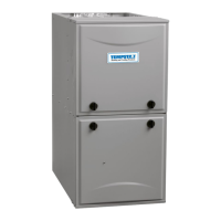
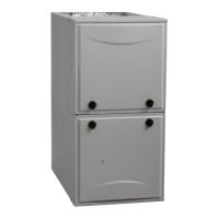
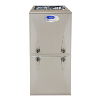
F80CTL and G80CTL
80% Variable–Speed
Category I, Non-Condensing, 33-1/3 in. Gas Furnace
(Series A)
Use of the AHRI Certified TM Mark indicates
a manufacturer’s participation in the program.
For verification of certification for individual
products, go to www.ahridirectory.org .


 Loading...