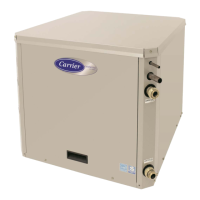
GZ Series
Geothermal System
Sizes 024, 036, 048, 060, 072
Installation Instructions
NOTE: Read the entire instruction manual before starting the installation.
TABLE OF CONTENTS
PAGE NO.
SAFETY CONSIDERATIONS 1.....................
INSTALLATION RECOMMENDATIONS 2...........
APPLICATION CONSIDERATIONS 3................
Geothermal Systems 3............................
Open Loop Well Water Systems 4...................
MATCHED SYSTEM 7.............................
REFRIGERANT LINES 7...........................
WATER PIPING 9..................................
Loop Pump Connections 9........................
Water Solenoid Valves 9..........................
Flow Regulator Valves 9..........................
Typical Open Loop Piping 10.......................
HRP Water Piping 11..............................
ELECTRONIC THERMOSTAT INSTALLATION 12.....
Field Connections 12..............................
ELECTRICAL 13...................................
FACTORY INSTALLED FEATURES 15................
Heat Recovery Package (HRP) 15....................
FIELD INSTALLED ACCESSORIES 15................
Liquid Line Solenoid (LLS) Accessory 15.............
Outdoor Air Temperature Sensor (OAT) 16.............
Compressor Start Accessories 16.....................
PRE START-- UP CHECKLIST 17.....................
UNIT START--UP 17.................................
USER INTERFACE QUICK SET--UP 17................
UI SYSTEM INITIAL POWER UP AND CHECKOUT 18.
SYSTEM VERIFICATION 18.........................
UPM SEQUENCE OF OPERATION FLOW CHART 18...
SYSTEM FUNCTION & SEQUENCE OF OPERATION 20
Communication and Status Function Lights 20..........
Time Delays 20..................................
Compressor Operation 20..........................
Safety Devices and UPM Board 20...................
TIMER SPEEDUP/TEST MODE 22....................
AUXILIARY HEAT LOCKOUT 22....................
BLOWER PERFORMANCE DATA TABLE 23..........
WATER SIDE PRESSURE DROP (PSIG) TABLE 24......
OPERATING TEMP. AND PRESSURES TABLES 25.....
TROUBLESHOOTING 30
............................
Fault Code Table 30...............................
Troubleshooting Units for Proper Switching
Between Low & High Stages 31.....................
Systems Communication Failure 31..................
MODEL PLU G 31...................................
SERVICE TOOL 32.................................
HRP TROUBLESHOOTING 32.......................
10K TEMPERATURE SENSOR RESISTANCE TABLE 33
MAINTENANCE 34.................................
Information in these installation instructions pertains only to GZ
series units.
SAFETY CONSIDERATIONS
Improper installation, adjustment, alteration, service, maintenance,
or use can cause explosion, fire, electrical shock, or other
conditions which may cause death, personal injury, or property
damage. Consult a qualified installer, service agency, or your
distributor or branch for information or assistance. The qualified
installer or agency must use factory--authorized kits or accessories
when modifying this product. Refer to the individual instructions
packaged with the kits or accessories when installing.
Follow all safety codes. Wear safety glasses, protective clothing,
and work gloves. Use quenching cloth for brazing operations.
Have fire extinguisher available. Read these instructions
thoroughly and follow all warnings or cautions included in
literature and attached to the unit. Consult local building codes and
current editions of the National Electrical Code (NEC) NFPA 70.
In Canada, refer to current editions of the Canadian electrical code
CSA 22.1.
Recognize safety information. This is the safety-- alert symbol
!
!
When you see this symbol on the unit and in instructions or
manuals, be alert to the potential for personal injury. Understand
these signal words; DANGER, WARNING, and CAUTION. These
words are used with the safety --alert symbol. DANGER identifies
the most serious hazards which will result in severe personal injury
or death. WARNING signifies hazards which could result in
personal injury or death. CAUTION is used to identify unsafe
practices which would result in minor personal injury or product
and property damage. NOTE is used to highlight suggestions
which will result in enhanced installation, reliability, or operation.
ELECTRICAL SHOCK HAZARD
Failure to follow this warning could result in personal injury
or death.
Before installing, modifying, or servicing system, main
electrical disconnect switch must be in the OFF position.
There may be more than 1 disconnect switch. Lock out and
tag switch with a suitable warning label.
!
WARNING
!
WARNING
UNIT OPERATION AND SAFETY HAZARD
Failure to follow this warning could result in personal injury
or equipment damage.
PuronR refrigerant systems operate at higher pressures than
standard R --22 systems. Do not use R-- 22 service equipment
or components on PuronR refrigerant equipment.