1
ER VCCSVA1100 ER VCCSHA1100
HRVCCSVA1100 HRVCCSHA1100
ENERGY/HEAT RECOVERY VENTILAT OR
Installation, Start--up,
and Operating Instructions
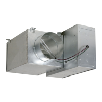
A05229
Fig. 1 -- ERV/HRV Unit (Top Port)
A05330
Fig. 2 -- ERV/HRV Unit (Side Port)
NOTE: Read the entire instruction manual before starting the
installation.
SAFETY CONSIDERATIONS
Installation and servicing of this equipment can be hazardous due to
mechanical and electrical components. Only trained and qualified
personnel should install, repair, or service this equipment.
Untrained personnel can perform basic maintenance functionssuch
as cleaning and replacing air filters. All other operations must be
performed by trained service personnel. When working on this
equipment, observe precautions in the literature, on tags, and on
labels attached to or shipped with the unit and other safety
precautions that may apply.
Follow all safety codes. Installation must be in compliance with
local and national building codes. Wear safety glasses, protective
clothing, and work gloves. Have fire extinguisher available. Read
these instructions thoroughly and follow all warnings or cautions
included in literature and attached to the unit.
Recognize safety information. This is the safety--alert symbol
!
!
When you seethissymbolon theunitandin instructions ormanuals,
be alert to the potential for personal injury.
Understand these signal words; DANGER, WARNING, and
CAUTION. These words are used with the safety--alert symbol.
DANGER identifies the most serious hazards which will result in
severe personal injury or death. WARNING signifies hazards which
could result in personal injury or death. CAUTION is used to
identify unsafe practices which ma y result in minor personalinjury
or product and property damage. NOTE is used to highlight
suggestions which will result in enhanced installation, reliability, or
operation.
INTRODUCTION
The Energy/Heat Recovery Ventilator (ERV/HRV) is used to
exchange indoor stale airwith outside fresh air. The unit isequipped
with a special energy/heat recovery core which transfers both
sensible and/or latent heat between the fresh incoming air and stale
exhaust air. The cross--flow design core allowsentering and leaving
air streams to transfer heat and/or latent energy without mixing (See
Fig. 14).
The model operates at 2 airflows, 50 CFM in low speed and 100
CFM in high speed. This unit comes in two configurations, vertical
or horizontal. Special attention should be given to duct application,
balancing the ERV/HRV, and locating unit for easy access and
routine maintenance.
INSTALLATION CONSIDERATIONS
Step 1.—Inspect Equipment
Move carton to final installation location. Remove ERV/HRV from
carton taking care not to damage unit. Remove all packaging and
inspect unit for damage. Remove parts bag from inside unit. File
claim with shipping company if shipment is damaged or
incomplete. Check to make sure ERV/HRV unit matches Fig. 1 or
Fig. 2.
Step 2.—Select Location
The ERV/HRV should be located in a conditioned space and in
close proximity to a fused power source. It should be easily
accessible for routine maintenance.
If ERV/HRV is installed independent of a forced-- air system, unit
should be located near the center of the air distribution system. If
ERV/HRV is installed in conjunction with a forced--air system, unit
should be located next to (or close to) the indoor equipment.