HEATING & COOUNG
Visit www.carrier.cmn
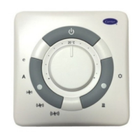
SYSTXCCUID01
Infinity Control TM
Installation and Start-Up Instructions
Infinity Control TM
SYSTXCCUID01
A03149
NOTE: Read the entire instruction manual before starting the
installation.
This symbol =-> indicates a change since the last issue.
TABLE OF CONTENTS
SAFETY CONSIDERATIONS ..................................................... 1
INTRODUCTION .......................................................................... 1
INSTALLATION AND START-UP OVERVIEW ...................... 1
INSTALLATION ........................................................................... 2
INITIAL POWER-UP .................................................................... 5
QUICK START .............................................................................. 6
INSTALL / SERVICE MENUS .................................................... 7
OPERATIONAL INFORMATION ............................................. 11
TROUBLESHOOTING ............................................................... 12
SAFETY CONSIDERATIONS
Read and follow manufacturer instructions carefully. Follow all
local electrical codes during installation. All wiring must conform
to local and national electrical codes, hnproper wiring or installa-
tion may damage Infinity Control System. Recognize safety
information. This is the safety-alert symbol Z_x • When you see this
symbol on the equipment and in the instruction manual, be alert to
the potential for personal injury. Understand the signal words
DANGER, WARNING, and CAIfTION.
These words are used with the safety-alert symbol. DANGER
identifies the most serious hazards, which will result in severe
personal injury or death. WARNING signifies a hazard, which
could result in personal injury or death. CAUTION is used to
identify unsafe practices, which would result in minor personal
injury or product and property damage. NOTE is used to highlight
suggestions which will result in enhanced installation, reliability,
or operation.
INTRODUCTION
The Infinity System consists of intelligent communicating com-
ponents (User Interface, variable speed furnace or fan coil, AC or
HP), which continually communicate with each other via a
four-wire connection called the ABCD bus. Conventional 24-volt
signals on dedicated wires are not needed. Commands, operating
conditions, and other data are passed continually between the
components over the ABCD bus. The result is a new level of
comlbrt, versatility, and simplicity.
An Infinity System consists of a Infinity Control TM (themmstat
plus much more) and an Infinity furnace or fan coil. All Infinity
furnaces or ban coils are variable-speed and nmlti stage for
maximum flexibility, efficiency, and comlbrt. They support con-
trolled ventilation, humidification, dehumidification, and air qual-
ity control. Either an Infinity dual capacity (communicating), or a
standard 24 vac controlled outdoor unit may be used.
When using conventional outdoor units, the Infinity furnace or fan
coil provides the 24 volt signals needed to control them. Also, the
Infinity Network Interface Module (NIM) allows connection of a
conventional HRV or ERV without the need for a separate wall
control.
All system components are controlled through the wall mounted
Infinity Control TM, which replaces the conventional thermostat and
provides the homeowner with a single wall control for all the
features of the system.
INSTALLATION AND START-UP OVERVIEW
This instruction covers installation of the Infinity Control TM only.
Physical installation instructions for the indoor, outdoor equipment
and accessories are provided with each unit.
Setup, commissioning, operation, and troubleshooting of the
Infinity System is covered only in this installation instruction. It is
your guide to connecting the system components and commission-
ing the system once all the physical components are installed.
Special screen prompts and start-up capabilities are provided in the
Infinity System to simplify and lead you through the initial
connnissioning of the system. So:
Install the Infinity ControV M according to this instruction.
Install the indoor unit, outdoor unit, and accessories according
to their instructions.
Wire the complete system according to this instruction.
Setup, commission, and operate the system according to this
instruction to assure yourself a smooth and trouble free
start-up.
Manufacturer reserves the right to discontinue, or change at any time, specifications or designs without notice and without incurring obligations.
_m PC 101 Catalog No 809-50020 Printed in USA. Form UID01-1Sl Pg 1 01-04 Replaces: NEW
isc