Specifications subject to change without notice.
Read and become familiar with these instructions before beginning
installation.
SAFETY CONSIDERATIONS
Read these instructions thoroughly and follow all warnings or cautions
included in the literature and attached to the unit. Consult local building codes
and National Electrical Code (NEC) for special requirements. Recognize
safety information.
This is the safety-alert symbol . When you see this symbol on the unit and
in instructions or manuals, be alert to the potential for personal injury.
Understand these signal words: DANGER, WARNING, and CAUTION.
These words are used with the safety-alert symbol. DANGER identifies the
most serious hazards which will result in severe personal injury or death.
WARNING signifies hazards which could result in personal injury or death.
CAUTION is used to identify unsafe practices which may result in minor
personal injury or product and property damage. NOTE is used to highlight
suggestions which will result in enhanced installation, reliability, or operation.
TABLE OF CONTENTS
PAGE
SAFETY CONSIDERATIONS........................................................1
OVERVIEW.....................................................................................1
DIMENSIONS..................................................................................2
CLEARANCES ................................................................................2
INSTALLATION .............................................................................3
SYSTEM CONFIGURATION SCENARIOS .................................3
WIRING ...........................................................................................8
DIP SWITCHES CONFIGURATION.............................................11
WIRING DIAGRAM .......................................................................13
APPENDIX 1 - COMPATIBILITY CHART...................................14
APPENDIX 2 - PIPING ADAPTER BUSHINGS/REDUCERS.....15
APPENDIX 3 - FV4C TRANSFORMER........................................15
APPENDIX 4 - ADDITIONAL REFRIGERANT CHARGE FOR
CONVENTIONAL FAN COILS .....................................................15
APPENDIX 5 - FV4C AIRFLOW DELIVERY ..............................16
OVERVIEW
The 24V INTERFACE KIT is used to connect:
A Single or Multi-zone Ductless System to a 3rd party single stage
conventional thermostat.
A Single Zone Ductless Condensing Unit 38MA*R with an approved
Fan Coil. For other applications, consult your Ductless representative.
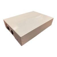
Fig. 1 —24V Interface
NOTES: Images are for illustration purposes only. Actual models may be
slightly different.
Table 1 —Kit Contents: Confirm the following parts are included
Table 2 — Field Supplied Components: Prepare the following assemblies on site
ELECTRICAL SHOCK HAZARD
Failure to follow this warning could result in personal injury or death.
Before beginning any modification or installation of this kit, be sure
the main electrical disconnect is in the OFF position.
Ensure power is disconnected to the fan coil unit. On some systems
both the fan coil and the outdoor unit may be on the same disconnect.
Tag the disconnect switch with a suitable warning label. There may
be more than one disconnect.
WARNING
EQUIPMENT DAMAGE HAZARD
Failure to follow this warning may result in equipment damage.
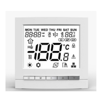
Do not install the wired controller in an area subjected to excessive
steam, oil or sulfide gas. Doing so may cause the controller to deform
and/or fail.
CAUTION
INSTALLATION
Entrust the distributor or authorized professionals to install the unit.
Installation by unskilled persons may lead to improper installation,
electric shock, or fire. Re-installation must be performed by
authorized professionals. Non-compliance may lead to electric shock
or fire.
CAUTION
No. Description Qty Remarks
1 Control box 1 N/A
2 Installation Manual 1 N/A
3 Screws 3 M4X20 (for wall mounting)
4 Wall Anchors 3 For wall mounting
7
Return Air Thermistor Assembly
(Hybrid Solutions) (RCD part
number 11201007003448)
1
Required and installed near
or on the unit and on the air
inlet side
8
16ft. (5m) Return Air Thermistor
Assembly Extension Wires (RCD
part number 17401204010126)
1
For a Return Air
Temperature Sensor on
Hybrid Solutions
No. Description Qty Type Remarks
1 Switch Box 1 N/A N/A
2
Wiring Tube (insulating sleeve
and tightening screw)
1 N/A N/A
KSAIC0301230 24V Interface Kit
for Ductless Systems and Hybrid Solutions
Installation Instructions