Non-Programmable Thermostats
Installation, Start-Up, and Operating Instructions
NOTE: Read the entire instruction manual before starting the
installation.
This symbol → indicates a change since the last issue.
SAFETY CONSIDERATIONS
Read and follow manufacturer instructions carefully. Follow all
local electrical codes during installation. All wiring must conform
to local and national electrical codes. Improper wiring or installa-
tion may damage thermostat.
Recognize safety information. This is the safety-alert symbol
.
When you see this symbol on the equipment and in the instruction
manual, be alert to the potential for personal injury.
Understand the signal words DANGER, WARNING, and CAU-
TION. These words are used with the safety-alert symbol. DAN-
GER identifies the most serious hazards which will result in severe
personal injury or death. WARNING signifies a hazard which
could result in personal injury or death. CAUTION is used to
identify unsafe practices which would result in minor personal
injury or product and property damage.
INTRODUCTION
Carrier thermostats are wall-mounted, low-voltage thermostats
which maintain room temperature by controlling the operation of
a heating and air conditioning system. Separate heating and
cooling setpoints, plus auto changeover provide maximum comfort
and flexibility. Batteries are not required; temperature and mode
settings are preserved with the power off.
INSTALLATION CONSIDERATIONS
Power
Note that all thermostat models require no batteries and are not
"power stealing". They do require 24vac (both R and C terminals)
to be connected for proper operation. Thermostat will not operate
without these 2 connections.
Models
There are 3 different models. The 9th and 10th letters of the part
number indicate the model. These 2 letters also appear on the
package and on the circuit board. Be sure to have the proper
thermostat for the intended application. Models are:
AC — 1-stage cool, 1-stage heat for AC systems only.
HP — 1-stage cool, 2-stage heat for either HP, or AC with 2-stage
heat.
2S — 2-stage cool, 2-stage heat for 2-speed AC systems, or
2-stage cool, 3-stage heat for 2-speed HP systems.
Use each only for its intended purpose. See Table 1.
INSTALLATION
Step 1—Thermostat Location
Thermostat should be mounted:
• Approximately 5 ft (1.5m) from floor.
• Close to or in a frequently used room, preferably on an inside
partitioning wall.
• On a section of wall without pipes or duct work.
Thermostat should NOT be mounted:
• Close to a window, on an outside wall, or next to a door leading
to the outside.
• Exposed to direct light and heat from a lamp, sun, fireplace, or
other temperature-radiating object which may cause a false
reading.
• Close to or in direct airflow from supply registers and return-air
grilles.
• In areas with poor air circulation, such as behind a door or in
an alcove.
Step 2—Select Model and Jumper
AC Model (1-stage cool, 1-stage heat) is to be used for single-
stage heating and/or cooling applications only. It CANNOT be
used with optional outdoor temperature sensor. (See Table 1 and
Fig. 2, 3, 4, 14, and 19.)
HP Model (1-stage cool, 2-stage heat) can be used with a
single-speed heat pump (HP), or an air conditioner (AC) with a
2-stage furnace or fan coil. A resistor (R19) serves as a HP/AC
selector jumper. This thermostat comes configured from the
factory as a heat pump thermostat. Leave R19 installed for HP
operation. Cut and discard for AC operation. When AC operation
is selected, the O/W2 terminal is converted from a reversing valve
output (O) to a second-stage heat output (W2). This output can be
used to control 2-stage furnaces or 2-stage electric heat in fan coils.
(See Table 1 and Fig. 5, 6, 7, 15, 17, and 21.)
2S Model is for 2-speed compressor HP and AC systems only.
Output Y1 controls compressor low speed and output Y/Y2
controls compressor high speed. Jumper resistor R19 serves as
HP/AC selector exactly as described above for HP model. (See
Table 1 and Fig. 8 through 13, 16, and 18.)
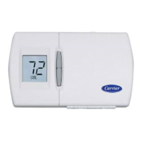
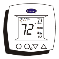
HEIGHT (IN.) WIDTH (IN.) DEPTH (IN.)
3-1/2 5-3/4 1-3/8
Fig. 1—Carrier Non-Programmable Thermostat
A98422
Visit www.carrier.com
Manufacturer reserves the right to discontinue, or change at any time, specifications or designs without notice and without incurring obligations.
Book 1 4
Tab misc. misc.
PC 101 Catalog No. 03TS-TA5 Printed in U.S.A. Form TSTAT-16SI Pg 1 10-98 Replaces: TSTAT-14SI