– 9 –
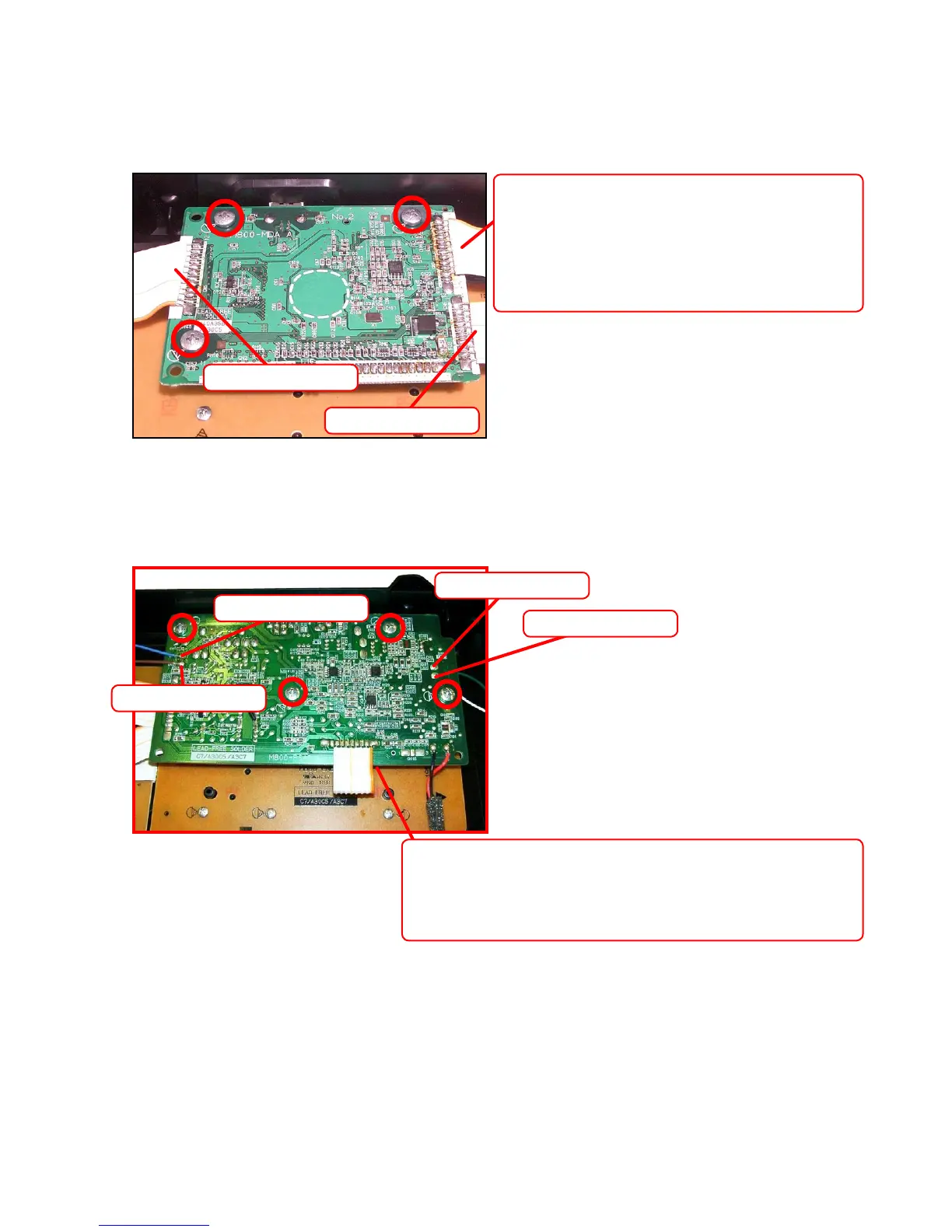
6. To remove the main PCB (M800-MDA1).
6-1. Remove three screws on the PCB (M800-MDA1).
6-2. Remove three cables by soldering.
6-3. Remove the PCB (M800-MDA1).
7. To remove the sub PCB (M800-PSA1).
7-1. Remove four screws on the PCB (M800-
PSA1
).
7-2. Remove one cable by soldering.
7-3. Remove four lead wires by soldering.
7-4. Remove the PCB (M800-
PSA1
).
Cable (CN6)
Cable (CN5)
Read wire (Brown)
Read wire (Blue)
Read wire (Green)
Read wire (White)
Cable (CN3)
Precaution while assembling the main Connector 3.
Number of pins on the PCB and pins on the cable
are different.
Start connecting from the NO.1 pin whose color is
orange.
Cable (CN106)
Precaution while assembling the main Connector 106.
Number of pins on the PCB and pins on the cable are different.
Start connecting from the NO.1 pin whose color is orange.
 Loading...