— 6 —
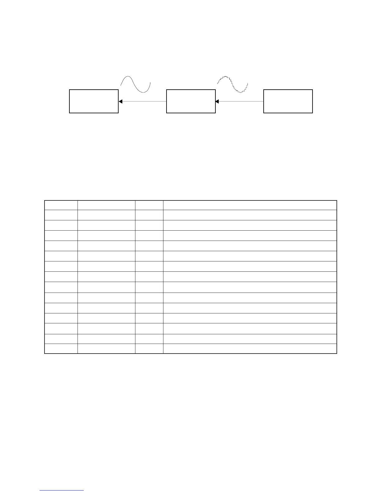
FILTER BLOCK
Since the sound signals from the CPU is stepped waveforms, the filter block is added to smooth the waveforms.
POWER AMPLIFIER (IC201: TA8248K)
The power amplifier is a two-channel amplifier with standby switch.
The following table shows the pin function of IC201.
Pin No. Terminal In/Out Function
1 NC — Not used
2 B.S.2 — Terminal for a bootstrap capacitor
3 OUT2 Out Channel 2 output
4 VCC In +9 V source
5 OUT1 Out Channel 1 output
6 B.S.1 — Terminal for a bootstrap capacitor
7 Power GND In Ground (0 V) source
8 Stand by In Power control signal input. 0 V: Off, +9 V: On
9 DC — Terminal for a decoupling capacitor
10 NF1 In Negative feedback input
11 IN1 In Channel 1 input
12 IN2 In Channel 2 input
13 NF2 In Negative feedback input
14, 15 Pre GND In Ground (0 V) source
Amp.
TA8248K
Filter
Block
CPU
MSM6755B-17
 Loading...