— 13 —
■ Procedure
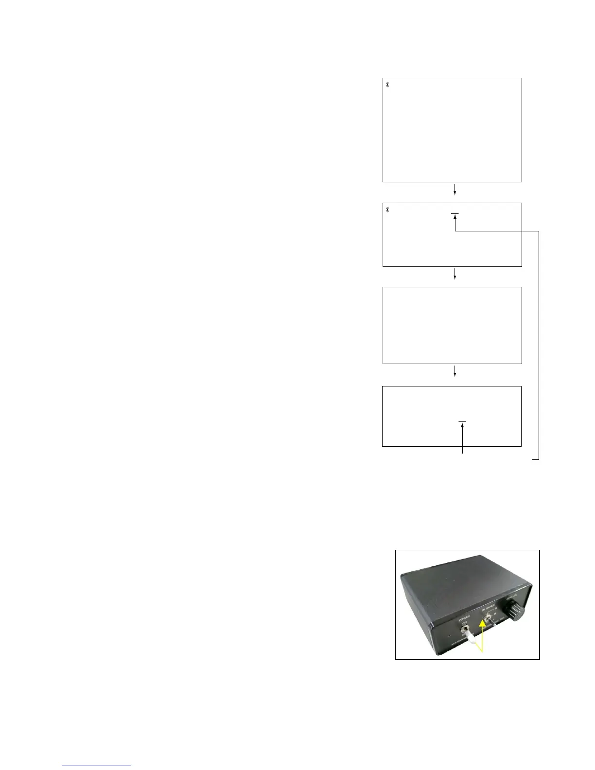
1. Camera setting
a) Turn the power on while pressing MENU and DISP.
After pressing “Right” key twice, press MENU.
Figure (a) appears.
b) Select “8 : ADJ_TEST” and then press SET.
(See Figure (b).)
c) Next, select “1. VCOM” and then press SET.
(See Figure (c).)
2. Connecting the TOOL
a) Place two 9-volt alkaline batteries in C2719.
b)
Connect the output terminal of C2719 to the channel terminal of the oscilloscope by the BNC-BNC cable.
c) Connect the input terminal to the Photo Diode by the BNC cable.
d) Turn the oscilloscope and C2719 on.
* Pull the ON/OFF switch of C2719 this way and raise/lower it. (See below Figure.)
d) Pressing SET causes the right figure to appear.
(See Figure (d).)
1 :VERSION INFO
2 :VIDEO OUT
3 :USB TCC TEST
4 :TEST MENU
5 :BEEP TEST
6 :TASK-2 TEST
7 :ROM UPDATE
8 :ADJ TEST
9 :REC-INFO
10 :TEST SCRIPT
11 :LAST MEMOR
Y
1:VCOM 7f
2:SHUT
3:AWB
.
.
.
VCOM ADJ START?
<<START>>
PUSH OK KEY?
<<STOP>>
PUSH PW KEY?
OK -> Register Write
VCOM = 0x7f
This value is an example and differs by products.
Figure (a)
Figure (b)
Figure (c)
Figure (d)
 Loading...