Home
Casio
Electronic Keyboard
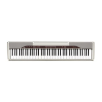
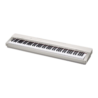
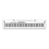
PX-110
Casio PX-110 Service Manual
4
of 1
of 1 rating
28 pages
Give review
Manual
Specs
To Next Page
To Next Page
To Previous Page
To Previous Page
Loading...
— 9 —
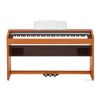
* Caution while assembling
Place the cable in the groove.
■
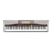
Removing the side case on the right.
14.
Remove the side case on the right.
■
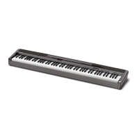
Removing the side case on the left, the PCB (M403-JKA1) and the power switch.
15.
Remove the side case on the left.
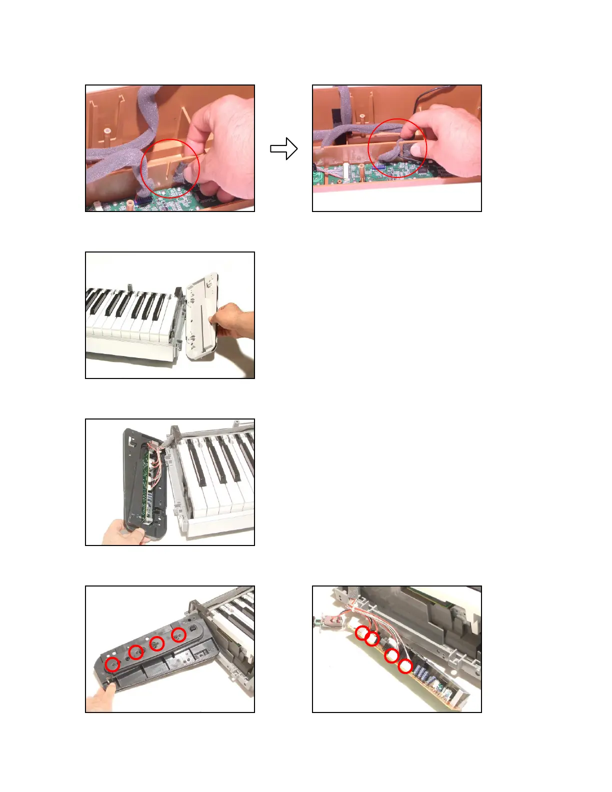
16.
Remove 4 screws.
17.
Remove 4 connectors and then the PCB (M403-JKA1).
10
12
Table of Contents
Table of Contents
2
Specifications
3
Block Diagram
4
Circuit Description
5
Printed Circuit Board
7
Disassembly
9
Diagnostic Program
14
Schematic Diagrams
16
Exploded View
23
Parts List
24
Other manuals for Casio PX-110
Function Guide
65 pages
4
Based on 1 rating
Ask a question
Give review
Questions and Answers:
Need help?
Do you have a question about the Casio PX-110 and is the answer not in the manual?
Ask a question
Casio PX-110 Specifications
General
Brand
Casio
Model
PX-110
Category
Electronic Keyboard
Language
English
Related product manuals
Casio Privia PX-110
32 pages
Casio PX-130
62 pages
Casio PRIVIA PX-130
36 pages
Casio Privia PX-100
31 pages
Casio PX-300
29 pages
Casio PX-700
29 pages
Casio PX-410R
34 pages
Casio PX-330BK
80 pages
Casio Privia PX-310
39 pages
Casio Privia PX-800
53 pages
Casio Privia PX-400R
49 pages
Casio keyboard PX-320
62 pages

 Loading...