1
DANGER s PELIGRO
132C2280-3D
TO ERASE ALL
RECEIVER CODES
1. Press and HOLD
receiver orange
ERASE button
6 seconds. Indicator
light will turn ON.
2. Release button
when light turns OFF.
CANADA:
PART NO.: NO. DE PIEZA:
DATE:
THE CHAMBERLAIN
GROUP, INC., USA
Ensamblado en México
Assembled in Mexico
ELIMINACIÓN DE
TODOS LOS CÓDIGOS DEL
RECEPTOR
1. MANTENGA PRESIONADO
el botón naranja "ERASE"
del receptor durante 6
segundos. La luz del
indicador se encenderá.
2. Suelte el botón cuando la
luz se apague.
DANGER s PELIGRO
132C2280-3D
TO ERASE ALL
RECEIVER CODES
1. Press and HOLD
receiver orange
ERASE button
6 seconds. Indicator
light will turn ON.
2. Release button
when light turns OFF.
CANADA:
PART NO.: NO. DE PIEZA:
DATE:
THE CHAMBERLAIN
GROUP, INC., USA
Ensamblado en México
Assembled in Mexico
ELIMINACIÓN DE
TODOS LOS CÓDIGOS DEL
RECEPTOR
1. MANTENGAPRESIONADO
el botón naranja "ERASE"
del receptor durante 6
segundos. La luz del
indicador se encenderá.
2. Suelte el botón cuando la
luz se apague.
Before you begin
1
Installation
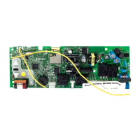
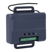
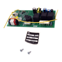
RECEIVER LOGIC BOARD REPLACEMENT
Model 050ACTWF
1.2 To maintain your warranty, place the
provided label over the existing label
on the end panel of the garage door
opener.
1.1 Remove the light lens by pulling the
top sides of the light lens and rotate the
light lens down. Squeeze the light lens
clips to remove lens from end panel.
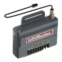
Your garage door opener has an internal gateway located on the receiver logic board. After installing the new receiver logic board, use the MyQ
®
serial number found on the provided label to add your
garage door opener to your MyQ
®
account. The products illustrated in the instructions are for reference. Your product may look different.
1.3 Disconnect power to the garage door
opener.
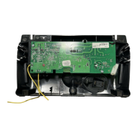
Remove the receiver logic board
2
2.1 Disconnect the wires from the quick-connect terminals (A).
Remove the receiver logic board end panel from the garage
door opener.
2.2 Unplug the wire harnesses from the receiver logic
board. You may need needle-nosed pliers to remove
the harnesses.
To prevent possible SERIOUS INJURY or
DEATH:
• Disconnect ALL electric and battery
power BEFORE performing ANY service
or maintenance.
To prevent damage to the receiver/logic
board, DO NOT touch printed circuit board
of replacement receiver/logic board during
installation.
ALWAYS wear protective gloves and eye
protection when changing the battery or
working around the battery compartment.
A
To insert or remove
the wires from the
terminal, push in the
tab with a
screwdriver tip.
Red
White
White
Grey
2.3 Remove the receiver
logic board from the
end panel by removing
the 2 screws and
releasing the 2 clips.
Screws
Wire clip
Clips
WARNING: This product can expose you to chemicals including lead, which are known to the State of California to cause cancer or birth
defects or other reproductive harm. For more information go to www.P65Warnings.ca.gov