Upgrading Cisco 4500, Cisco 4500-M, Cisco 4700, and Cisco 4700-M Memory 13
Memory Replacement Procedures
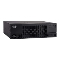
Figure 9 Cisco 4700-M and Newer Versions of the Cisco 4500-M Memory Component Locations
Replacing Main Memory SIMMs
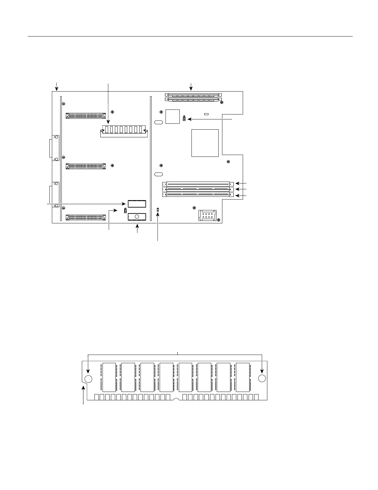
SIMMs are manufactured with a polarization notch to prevent them from being installed backward.
Figure 10 shows the polarization notch and locations of the alignment holes on a main memory
SIMM card. The main memory SIMM cards are installed with the connector edge down and the
component side facing in, as shown in the upper right corner of Figure 8 and Figure 9.
Figure 10 Main Memory SIMM
Main memory SIMM sockets
with correct SIMM orientation
Front of chassis
Motherboard
Shared-memory
SIMM and socket
H6665
System Flash memory 1
J5
J1
J6
System Flash memory 0
RxBoot Flash memory
Jumper in place enables
writing to Flash memory
Jump pins
1 and 2
Jump pins 1 and 2
ROM monitor
U78
NVRAM
Alignment holes
Connector edge
Polarization notch
H2407
 Loading...


