The following configuration restrictions apply to these APs' antennas:
For each slot, the antennas that the software calls "A" and "B" must be enabled•
Thus, if the Slot 0 radio is in use, external antennas must be connected to (at least) physical ports "A"
and "B"
•
And, if the Slot 1 radio is in use, external antennas must be connected to (at least) physical ports "D"
and "C"
•
No antenna may be enabled for a radio, unless all antennas that precede it in alphabetic order are
enabled. Thus, "antenna D" may not be enabled, unless antennas "C", "B" and "A" are enabled
•
Valid Configuration Options with RP-TNC Antennas
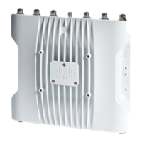
Thus, the C9115AXE, C9120AXE and C9120AXP access points support only the following external
antenna configurations, if using only the RP-TNC ports (without the DART-4):
If both Slot 0 and Slot 1 are enabled:•
Four external antennas connected to physical ports A, B, C and D, with all antennas oriented to
the same coverage area
•
Two external antennas aimed in one direction, connected to physical ports A and B - these will
be used by the Slot 0 radio, and two external antennas aimed in a different direction, connected
to physical ports C and D - used by the Slot 1 radio. In this configuration, the software should
be configured to have only antennas "A" and "B" enabled (for both radios)
•
If only Slot 0 is enabled•
At least two external antennas connected to physical ports A and B (optionally, with third [and
fourth] antennas connected to C [and D]), oriented in the same direction
•
The software should be configured with antennas "A" and "B" (optionally, "C" [and "D"])
enabled
•
If only Slot 1 is enabled•
At least two external antennas connected to physical ports D and C (optionally, with third [and
fourth] antennas connected to B [and A]), oriented in the same direction
•
The software should be configured with antennas "A" and "B" (optionally, "C" [and "D"])
enabled.
•
If there is a requirement that both the Slot 0 and Slot 1 radios have four antennas connected, with the
antennas oriented in different directions, then use a DART-4 connector. The antennas connected to the
DART-4 will be used by Slot 0, while the four RP-TNC antennas will be used by Slot 1.
 Loading...