7
Product Documentation and Compliance Information for the Cisco ISA 3000 Industrial Security Appliance
78-100733-01B0
To connect DC power:
Step 1
Locate the power connector on the ISA 3000 front panel.
Step 2
Identify the connector positive and return DC power connections. The connections are:
• + — Positive DC power connection
• - —Return DC power connection
Step 3
Measure two strands of twisted-pair copper wire (18-to-20 AWG) (2.6mm) long enough to connect to the DC power
source.
Step 4
Using an 18-gauge (1.02mm) wire-stripping tool, strip each of the two
twisted pair wires coming from each DC-input power source to 0.25 inch
(6.3 mm) ± 0.02 inch (0.5 mm). Do n ot strip more than 0.27 inch (6.8 mm)
of insulation from the wire. Stripping more than the recommended
amount of wire can leave exposed wire from the power connector after
installation.
Step 5
Remove the two captive screws that attach the power connector to the ISA 3000, and remove the connector.
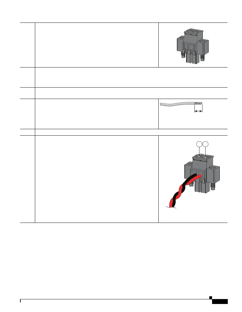
Step 6
On the power connector, insert the exposed part of the positive wire into
the connection labeled “+” and the exposed part of the return wire into the
connection labeled “–”. Make sure that you cannot see any wire lead. Only
wire with insulation should extend from the connector.
1 - Power source positive connection.
2 - Power source return connection.
331209
406053
2 1

 Loading...