EasyManua.ls Logo

Clevo NP50DE User Manual

Clevo NP50DE
106 pages
To Next Page IconTo Next Page
To Previous Page IconTo Previous Page
Page #34 background imageLoading...
Page #34 background image
Disassembly
2 - 10 Removing the Hard Disk Drive
2.Disassembly
4. Carefully lift and slightly slide the hard disk up.
5. Disconnect the hard disk assembly from the connector (Figure 6c).
6. Remove screws - and bracket from the hard disk (Figure 6d).
7. Reverse the process to install a new hard disk (do not forget to replace the screws).
3
4
5
6
7
8
c.
3
4
d.
7
6
5
8
3. HDD Assembly
7. HDD Bracket
8. HDD
•2 Screws
Figure 6
HDD Assembly
Removal (cont’d.)
c. Slide and lift the HDD as-
sembly to disconnect
from the connector.
d. Remove the screws and
bracket from the HDD.

Table of Contents

Question and Answer IconNeed help?

Do you have a question about the Clevo NP50DE and is the answer not in the manual?

Clevo NP50DE Specifications

General IconGeneral
BrandClevo
ModelNP50DE
CategoryLaptop
LanguageEnglish

Summary

Preface

Important Safety Instructions

Lists critical safety precautions for using electrical equipment.

Power Safety

Details power requirements and safety warnings for the notebook.

Battery Precautions

Highlights warnings for battery handling, charging, and disposal.

Introduction

Specifications

Lists detailed technical specifications for the notebook computer.

Disassembly

Maintenance Precautions

Lists safety precautions for disassembly and general maintenance.

Removing the Keyboard

Step-by-step guide for safely removing the laptop keyboard.

Removing the Battery

Step-by-step guide for safely removing the laptop battery.

Removing the M.2 SSD Module

Step-by-step guide for removing the M.2 SSD module.

Removing the Hard Disk Drive

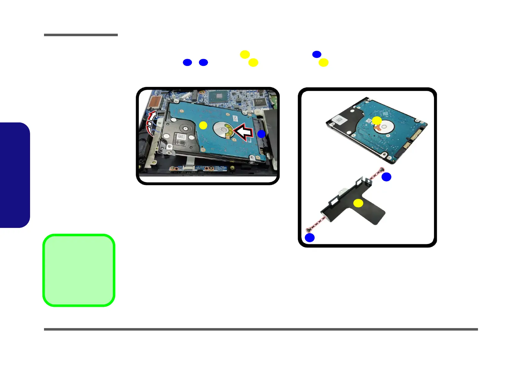
Step-by-step guide for removing the 2.5" SATA hard disk drive.

Removing the System Memory (RAM)

Step-by-step guide for removing and replacing RAM modules.

Removing the Wireless LAN Module

Step-by-step guide for removing the wireless LAN module.

Appendix A: Part Lists

Appendix B: Schematic Diagrams

System Block Diagram

High-level overview of the system's architecture.

VGA Frame Buffer Interface

Schematics for the VGA frame buffer interface connections.

VGA Frame Buffer A

Schematic diagrams for VGA Frame Buffer A.

VGA Frame Buffer B

Schematic diagrams for VGA Frame Buffer B.

VGA I/O

Schematics for VGA input/output interfaces.

NVIDIA Power Sequence

Diagram illustrating the power-on sequence for the NVIDIA GPU.

ALC293D

Schematic for the ALC293D audio codec.

M.2 WLAN+BT, PCIE4X SSD

Schematics for M.2 WLAN/BT and PCIe SSD modules.

USB, Charger

Schematics for USB ports and charger circuitry.

Card Reader / LAN RTL8411B

Schematics for the card reader and LAN controller.

HDD, TP, Audio, Hall Conn

Schematics for HDD, touchpad, audio, and hall sensor connections.

LED, CCD, TPM, Power SW Conn

Schematics for LED, CCD, TPM, and power switch connections.

KBC-ITE IT5570

Schematic for the KBC-ITE IT5570 keyboard controller.

VCore Output Stage

Schematics detailing the VCore voltage output stages.

AC_In, Charger

Schematics for AC power input and battery charging circuitry.

Audio Board

Schematics for the audio board components.

Related product manuals