quickstart guide
DM-TX-401-S/DM-TX-401-S2
www.crestron.com
888.273.7876 201.767.3400
Specifications subject to
change without notice.
DM-TX-401-S/DM-TX-401-S2
QUICKSTART DOC. 7258B (2031811) 11.12
DigitalMedia 8G™ Fiber Transmitter 401
Mounting the DM-TX-401-S/
DM-TX-401-S2
● DISPLAY PORT: Using a DisplayPort cable
(not included), connect the DISPLAY PORT
to a DisplayPort audio/video source.
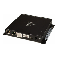
● DM OUT MMF/SC Port: (DM-TX-401-S
only) Using
CRESFIBER8G, CRESFIBER,
CRESFIBER-SINGLE-SC,
or generic OM3
fiber optic cable (not included), connect the
DM OUT MMF/SC port to the DM 8G
®
fiber
input of a DM
®
switcher, receiver/room
controller, or other DM device.
● DM OUT SMF/LC Port: (DM-TX-401-S2
only) Using
CRESFIBER8G-SM or
generic
G.652.D (or better) single-mode fiber optic
cable (not included), connect the DM OUT
SMF/LC port to the DM 8G SMF input of a
DM switcher, receiver/room controller, or
other DM device. For DM 8G SMF wiring,
the maximum transmission distance is 7.5
miles (12 km).
● LAN Port: Using an Ethernet cable (not
included), connect the 10BASE-T/
100BASE-TX LAN port to a local network
device.
● Ground: Connect the chassis ground lug to
earth ground (building steel).
● 24 VDC Power: Connect the 24 VDC
power jack to the external power pack
included with the transmitter.
1
For details, refer to the latest version of the DM-TX-401-S/S2
Operations and Installation Guide, Doc. 7257.
NOTE: For DigitalMedia 8G™ fiber
wiring, CRESFIBER8G is
recommended. Using CRESFIBER8G,
the maximum transmission distance is
1000 feet (~300 meters). Using
CRESFIBER/CRESFIBER-SINGLE-SC
or generic OM3 fiber optic cable, the
maximum transmission distance is 500
feet (~150 meters).
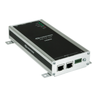
Connections in a Sample DM-TX-401-S Application
Mount the transmitter in the desired location
(for example, in a stationary rack or podium,
on a shelf, or in a movable lectern or AV cart).
If rack mounting is desired, use the ST-RMK
Rack Mount Kit (sold separately). For rack
mounting instructions, refer to the latest
version of the Rack Mount Kit: ST-RMK
Installation Guide (Doc. 5664), which is
available from the Crestron
®
Web site
(www.crestron.com/manuals).
2
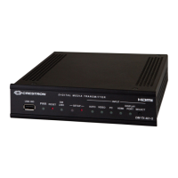
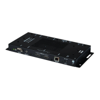
Connect the transmitter as required for the
application. Rear panel connections consist of
the following:
● AUDIO IN TRS Port: Using an unbalanced
3.5 mm TRS mini phone jack cable (not
included), connect the AUDIO IN TRS port
to an unbalanced audio source.
● Dual AUDIO IN RCA Ports: Using a
dual-channel RCA stereo audio cable (not
included), connect the AUDIO IN L and
R
ports to an unbalanced audio source.
● COM Port: Using a data communications
cable (not included), connect the 5-pin
COM terminal block to the device to be
controlled using RS-232 communication.
● IR Port: Using the Crestron IRP2 emitter
(not included), connect the 2-pin IR terminal
block to the IR input port of the device to be
controlled.
● VID Port: Using an RCA video cable (not
included), connect the VID port to a
composite video source.
● PC Port: Using a VGA cable (not
included), connect the PC port to an RGB,
component, S-video, or composite video
source.
● HDMI Port: Using an HDMI
®
cable (not
included), connect the HDMI port to an
HDMI audio/video source.
NOTE: Apply power after all
connections have been made.
1
Connecting the DM-TX-401-S/
DM-TX-401-S2
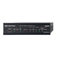
In addition, the front panel provides a USB HID
port. Using a USB cable (not included), connect
the USB HID port to a keyboard/mouse.