Macro-Tech
®
602/1202/2402 Power Amplifiers
Page 16
Reference Manual
Please follow the instruction in Section 3.3.2 and 3.3.3 if
the amplifier will be used in either Bridge-Mono or Par-
allel-Mono mode. Remember, do not use the Channel 2
input in either of these mono modes.
SOLVING INPUT PROBLEMS
Sometimes large infrasonic (subaudible) frequencies
are present in the input signal. These can damage loud-
speakers by overloading or overheating them. To at-
Input Wiring Tips
1. Use only shielded cable. Cables with
higher density shields are better. Spiral
wrapped shield is not recommended.
2. When using unbalanced lines, keep the
cables as short as possible. Avoid cable
lengths greater than 10 feet (3 meters).
3. Do not run signal cables together with
high-level wiring such as loudspeaker wires
or AC cords. This greatly lessens the chance
of hum or noise being induced into the input
cables.
4. Turn the entire system off before changing
connections. Turn level controls down
completely before powering the system back
up. Crown is not liable for damage incurred
when any transducer or component is
overdriven.
+
–
Balanced In
910
Ω
.003
F
µ
.015
F
µ
.018
F
µ
1.8 mH
2.5 mH
A
C
B
.015
F
µ
1.8 mH
D
Balanced Out
+
–
910
Ω
1.8 mH
2.5 mH
1.8 mH
+
–
Balanced In
Balanced Out
+
–
+
–
Balanced In
Balanced Out
+
–
+
–
Balanced In
Balanced Out
+
–
0.47 Film
0.47 Film
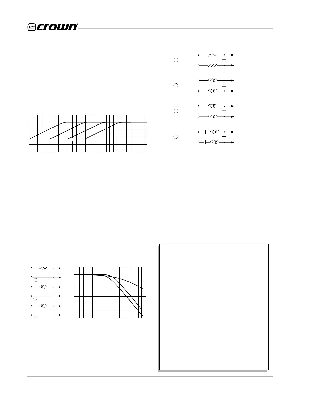
Fig. 3.12 Balanced RFI Filters
1 Hz 10 Hz 100 Hz 1 kHz 10 kHz
dB
0
–5
–10
–15
1 F
µ
.1 F
µ
.05 F
.01 F
µ
µ
Frequency
Fig. 3.10 Infrasonic Filter Capacitors
tenuate such frequencies, place a capacitor in series
with the input signal line. The graph in Figure 3.10
shows some capacitor values and how they affect the
frequency response. Use only low-leakage paper, mylar
or tantalum capacitors.
Another problem to avoid is the presence of large lev-
els of radio frequencies or RF in the input signal. Al-
though high RF levels may not pose a threat to the
amplifier, they can burn out tweeters or other loads that
are sensitive to high frequencies. Extremely high RF lev-
els can also cause your amplifier to prematurely acti-
vate its protection circuitry, resulting in inefficient
4 kHz 10 kHz 40 kHz 100 kHz
Frequency
dB
0
–10
–20
A
B
C
6 dB/octave
12 dB/octave
To
Amp
GND
To
Amp
GND
To
Amp
GND
Source
1.8 K ohm
.003
Fµ
.015
F
µ
.018
Fµ
3.9 mH
5 mH
600 ohm
Source
R
600 ohm
Source
R
A
C
B
Note: A low source impedance (R) can be
increased to 600 ohms with an appropriate resistor.
Fig. 3.11 Unbalanced RFI Filters
operation. RF can be introduced into the signal by local
radio stations and from the bias signal of many tape
recorders. To prevent high levels of input RF, install an
appropriate low-pass filter in series with the the input
signal. Some examples of unbalanced wiring for low-
pass filters are shown in Figure 3.11.
For balanced input wiring use one of the examples in
Figure 3.12. Filters A, B and C correspond to the unbal-
anced filters above. Filter D also incorporates the infra-
sonic filter described previously.
A third problem to avoid is hum. The two most common
sources of hum in an audio system are inductive cou-
pling and ground loops.
Inductive coupling can occur when input cables are
 Loading...