4 InstallatIon
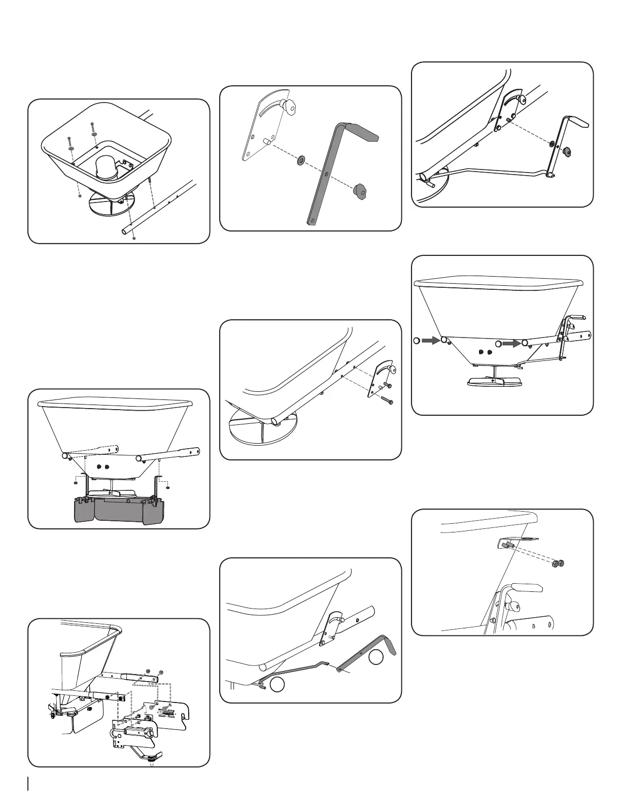
5. Attach the hopper assembly to the round
ends of the single frame tubes with four M6 x
40 bolts and washers found in hardware pack
3032810. Secure the rear bolts on each side
with hex nuts from hardware pack 3032810.
The front nuts will be installed later to secure
the material deflector. See Figure 2-8.
Figure 2-8
NOTE: The indented side of the tubes should
be facing in.
Material Deflector Assembly Installation
The material deflector must be used to focus the
dispersion of material away from the unit and
operator. To install the deflector assembly:
1. Line the deflector up so that the opening in
the deflector plates faces backward. Secure
the deflector to the front hopper/frame tube
bolts with two hex nuts from hardware pack
3032810. See Figure 2-9.
Figure 2-9
Attaching Hitch Bracket to Spreader Assembly
1. Use two 3/8-16 x 1.25 carriage bolts and two 3/8-16
locknuts from hardware pack 689-00510 per side
to attach the indented ends of the single frame
tubes, to the top of the Fast Attach Hitch Bracket.
See Figure 2-10.
Figure 2-10
Attaching Spreader Control Plate Assembly
1. Disassemble the control handle from the
control plate by removing the wing nut. Save
the control handle, washer and wingnut to
reinstall later. See Figure 2-11.
Figure 2-11
2. Use two M6 x 40 bolts and locknuts to attach
the control plate to the right side of the frame.
See Figure 2-12.
NOTE: The slot should face up, and the bolts
and locknuts should be secured through the
holes at the bottom corners of the plate.
Figure 2-12
3. Insert the control rod (hook side) into the
restrictor plate (beneath the hopper) from the
top down. See 1 in Figure 2-13.
4. Turn the control handle on its side and insert
the flattened (90° angle side) of the control rod
into the lower hole on the control handle. See
2 in Figure 2-13.
Figure 2-13
5. Reattach the control handle to the control
plate using the washer and wingnut previously
disassembled. See Figure 2-14.
Figure 2-14
6. If not already installed, insert plugs into rear
ends of the single frame tubes. See Figure 2-15.
Figure 2-15
7. Install the motor ON/OFF switch bracket onto
the right side of the hopper using two hex
screws, washers and locknuts. Thread the hex
screws through the washers, then through
the hopper. Secure the switch bracket to the
outside of the hopper with the locknuts. See
Figure 2-16.
Figure 2-16
 Loading...