43
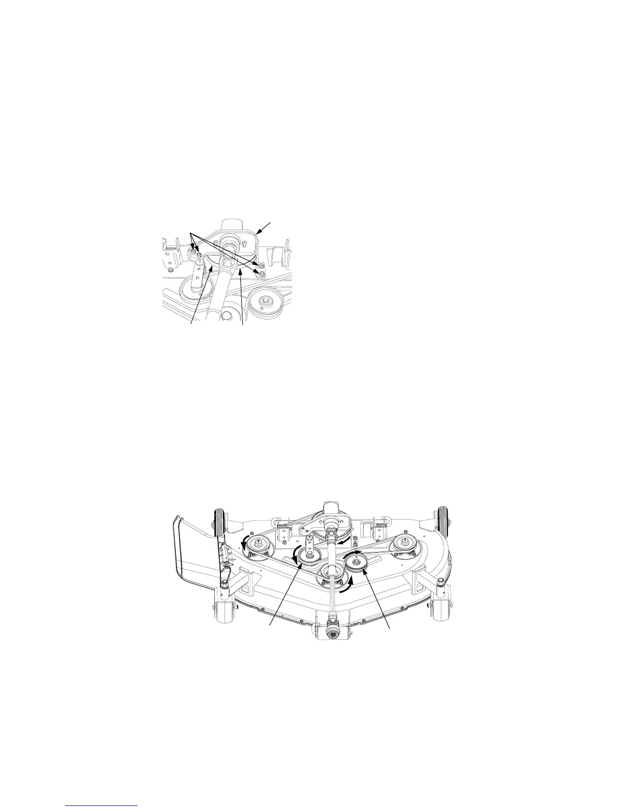
6. Remove the two hex flange lock
nuts and carriage bolts securing
the right side of the gear box
mounting bracket to the deck
plate (See Figure 51).
Figure 51
7. Lift the gear box/mounting
bracket assembly and slide the
belt off and underneath the drive
pulley.
8. Remove the belt from the deck.
Install new spindle belt
1. Lift the gear box/mounting
bracket assembly to install the
belt around the rear and left side
of the drive pulley, and through
the center opening of the mount-
ing bracket (See Figure 51).
2. Secure the gear box mounting
bracket with the four carriage
bolts and hex flange lock nuts.
3. Route the belt as follows (Refer to
Figure 52):
• around the right spindle pulley
• around the front of the center
spindle pulley
• around the rear of the fixed flat
idler pulley to the left spindle
pulley
• Route the backside of the belt
around the rear and right side of
the movable flat idler pulley
4. After making certain the belt is
properly engaged in each pulley,
insert the 3/8” drive ratchet
(breaker bar) into the idler arm
and pivot the movable flat idler
pulley toward the left side of the
deck to allow the spindle belt to
be rolled onto the left hand spin-
dle pulley. Refer to Figure 50.
5. Install the belt covers and secure
with the hex nuts and lock
washers.
Gear Box
Mtg. Bracket
Carriage Bolts
and Hex Flange
Lock Nuts
Drive Pulley
Spindle Belt
Figure 52
Movable
Flat Idler
Pulley
Fixed
Flat Idler
Pulley
 Loading...