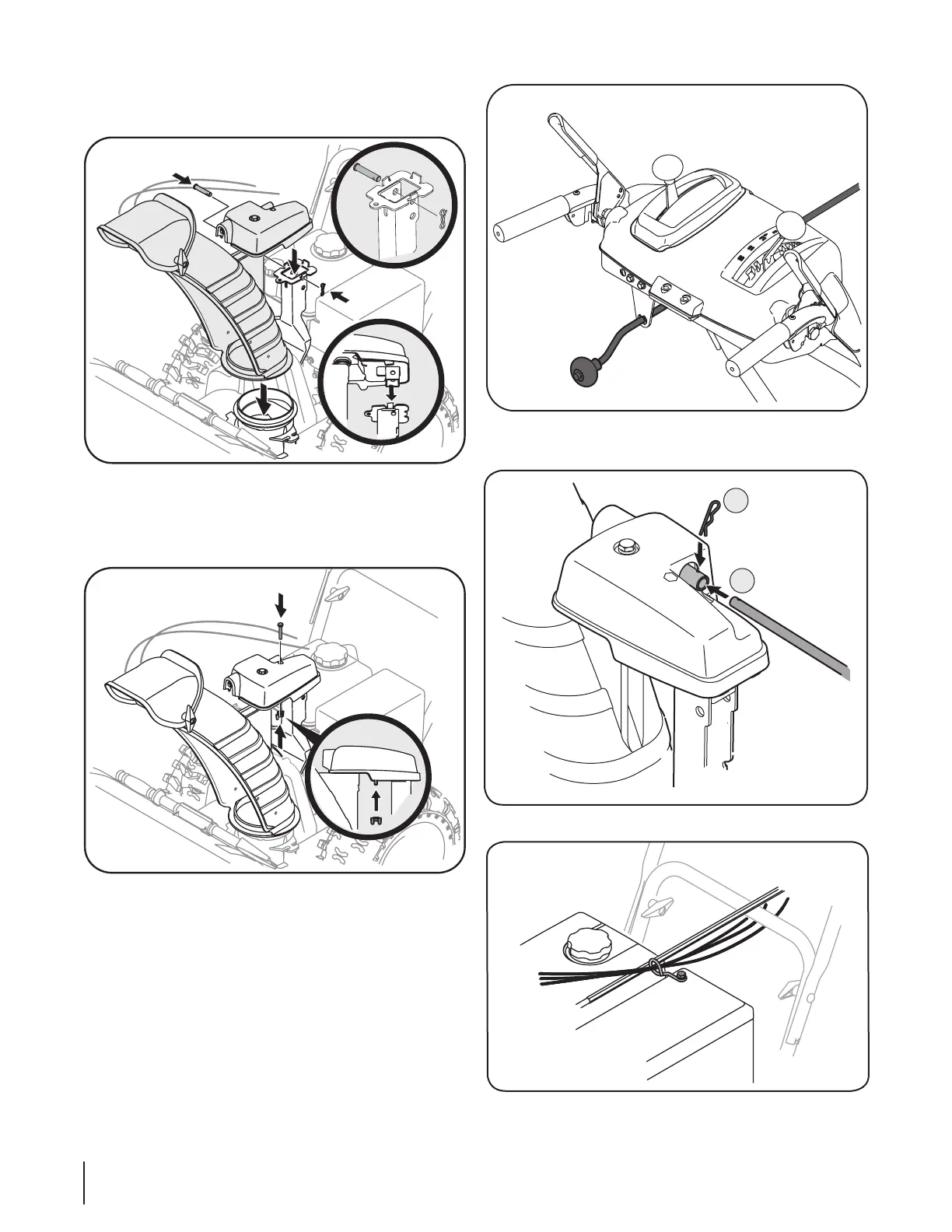
Fig. 3-8
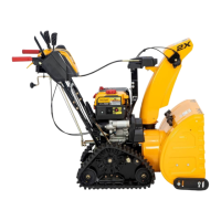
• Place chute assembly onto chute base and secure chute
control assembly to chute support bracket with clevis pin and
cotter pin removed earlier. See Fig. 3-4.
• Finish securing chute control assembly to chute support
bracket with wing nut and hex screw removed earlier. See
Fig. 3-5.
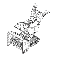
• Guide the chute crank rod through the bracket located on
the rear of the handle panel See Fig. 3-6.
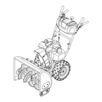
a. Remove the cotter pin and insert the chute crank rod
into the connector on the chute control assembly.
See Fig. 3-7.
b. Align the hole in the chute crank rod with the hole
in the connector, secure with cotter pin previously
removed.
• Check that all cables are properly routed through the cable
guide on the right side of the chute crank rod. See Fig. 3-8.
Fig. 3-5
Fig. 3-6
Fig. 3-7
Fig. 3-4
8 Section 3— ASSembly & Set-Up
 Loading...