Replacement of batteries located
in an OPERATOR ACCESS AREA
1. When replacing batteries, replace with
the same number of the following battery:
CyberPower/RB1290 for CP825AVRLCDG,
CP800AVR; CyberPower/RB1270B for
CP685AVRLCDG, CP685AVRG.
2. CAUTION! Risk of Energy Hazard, 12V,
maximum 9 Ampere-hour battery. Before
replacing batteries, remove conductive
jewelry such as chains, wrist watches, and
rings. High energy through conductive
materials could cause severe burns.
3. CAUTION! Do not dispose of batteries in a
fire. The batteries may explode.
4. CAUTION! Do not open or mutilate batter-
ies. Released material is harmful to the skin
and eyes. It may be toxic.
5. CAUTION! A battery can present a risk of
electrical shock and high short circuit cur-
rent. The following precautions should be
observed when working on batteries:
(1) Remove watches rings, or other metal
objects.
(2) Use tools with insulated handles.
CAUTION - RISK OF EXPLOSION IF BATTERY
IS REPLACED BY AN INCORRECT TYPE.
DISPOSE OF USED BATTERIES ACCORDING
TO LOCAL REGULATIONS.
TROUBLESHOOTING - continued
Problem Possible Cause Solution
Circuit breaker button is
projecting from the back of the
unit.
Circuit breaker has been tripped
due to an overload.
Turn the UPS o and unplug at
least one piece of equipment.
Wait 10 seconds, reset the circuit
breaker by pressing the button,
and then turn the UPS on.
The UPS does not perform
expected runtime.
Battery not fully charged.
Recharge the battery by leaving
the UPS plugged in.
Battery is worn out.
Contact CyberPower Systems
about replacement batteries at:
cyberpowersystems.com/support.
Additional troubleshooting information can be found at “Support” at www.CyberPowerSystems.com
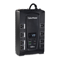
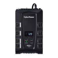
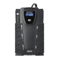
LOAD CAPACITY Meter: This meter displays
the approximate output load level of the UPS
battery outlets in 20% increments.
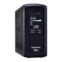
SENSITIVITY Meter: This meter displays the
sensitivity level of the UPS. It is to control the
sensitivity of the UPS to switch to Battery
Mode by selecting UPS shutdown voltage
range. When the sensitivity is increased, the
UPS will switch to Battery Mode with less
input power variation.
FAULT: The following number appears if there
is a problem with the UPS. Press the POWER
button to turn the UPS o.
DEFINITIONS FOR ILLUMINATED LED INDICATORS - continued TECHNICAL SPECIFICATIONS - continued
REPLACING THE BATTERY
TROUBLESHOOTING
Problem Possible Cause Solution
The UPS will not turn on.
The on/o switch is designed
to prevent damage from rapidly
turning it o and on.
Turn the UPS o. Wait 10 seconds
and then turn the UPS on.
The unit is not connected to an
AC outlet.
The unit must be connected to a
120V 60Hz outlet.
The battery is worn out.
Contact CyberPower Systems
about replacement batteries at:
cyberpowersystems.com/support.
Mechanical problem.
Contact CyberPower Systems at:
cyberpowersystems.com/support.
PowerPanel® Personal is inactive
(all icons are gray).
The USB cable is not connected.
Connect the USB cable to the UPS
unit and an open USB port on the
back of the computer.
The USB cable is connected to a
bad USB port.
Check for a dierent USB port and
plug the cable in.
The unit is not providing
battery power.
Shutdown your computer and turn
the UPS o. Wait 10 seconds and
turn the UPS back on. This should
reset the unit.
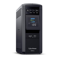
The USB power ports are not
providing power to the connect-
ed devices.
The USB power port has Over Cur-
rent Protection design. When the
total current of connected devices
is over 2.1A, the USB power ports
will stop providing power to the
connected devices.
Turn the UPS o and unplug at
least one piece of device connect-
ed to the USB power port and
then turn the UPS on.
TECHNICAL SPECIFICATIONS
Advanced Energy-Saving Design
The GreenPower UPS™ has a high-eciency charger, which makes it the most energy-ecient UPS in its class. The advanced high-frequency
charging system significantly improves charging eciency and conserves energy. As a result of this advanced design, the GreenPower UPS™
uses less energy compared to competitive models. The GreenPower UPS™ is manufactured in accordance with the Restriction on Hazardous
Substances (RoHS) directive making it one of the most environmentally-friendly UPS systems on the market today.
CYBERPOWER GREENPOWER UPS™ TECHNOLOGY
G
REEN
P
OWER
UPS
™
Energy-Saving Technology
This device complies with part 15 of the FCC rules. Operation is subject to the following two conditions: (1) this device may not cause harmful
interference, and (2) this device must accept any interference received, including interference that may cause undesired operation.
Note: This equipment has been tested and found to comply with the limits for a Class B digital device, pursuant to part 15 of the FCC
Rules. These limits are designed to provide reasonable protection against harmful interference in a residential installation. This equipment
generates, uses, and can radiate radio frequency energy and, if not installed and used in accordance with the instructions, may cause harmful
interference to radio communications. However, there is no guarantee that interference will not occur in a particular installation. If this equipment does
cause harmful interference to radio or television reception, which can be determined by turning the equipment o and on, the user is encouraged to try to
correct the interference by one or more of the following measures:
- Reorient or relocate the receiving antenna.
- Increase the separation between the equipment and receiver.
- Connect the equipment to an outlet on a circuit dierent from that to which the receiver is connected.
- Consult the dealer or an experienced radio/TV technician for help.
Warning: Changes or modifications not expressly approved by the party responsible for compliance could void the user’s authority to operate the equipment.
Canadian Compliance Statement
CAN ICES-3 (B)/NMB-3(B)
FCC COMPLIANCE STATEMENT
Please visit www.CyberPowerSystems.com for a copy of the Limited Warranty and Connected Equipment Guarantee.
Where Can I Get More Information?
The application of the United Nations Convention of Contracts for the International Sale of Goods is expressly excluded.
CyberPower is the warrantor under this Limited Warranty. For further information please feel free to contact CyberPower at:
Cyber Power Systems (USA), Inc. 4241 12th Ave E., STE 400, Shakopee, MN 55379;
call us at (877) 297-6937; or submit a web ticket online at cyberpowersystems.com/support.
Cyber Power Systems (USA), Inc. encourages environmentally sound methods for disposal and recycling of its UPS products.
Please dispose and/or recycle your UPS and batteries in accordance to the local regulations of your state.
LIMITED WARRANTY AND CONNECTED EQUIPMENT GUARANTEE
© 2022 CyberPower Systems (USA), Inc. PowerPanel® Personal is a trademark of Cyber Power Systems(USA) Inc.
All rights reserved. All other trademarks are the property of their respective owners.
6
7 8
5
INPUT Voltage Meter: This meter measures
the AC voltage that the UPS system is re-
ceiving from the utility wall outlet. The UPS
is designed to continuously supply connect-
ed equipment with stable output voltage. In
the event of a complete power loss, severe
planned power suppression, or over-voltage,
the UPS relies on its internal battery to supply
consistent 110/120 output voltage. The INPUT
voltage meter can be used as a diagnostic tool
to identify poor-quality input power.
OUTPUT Voltage Meter: This meter measure,
in real time, the AC voltage that the UPS
system is providing to the computer during
normal AC/Utility Power mode, and battery
backup mode.
ESTIMATED RUNTIME: This displays the run
time estimate of the UPS with the current
battery capacity and load.
NORMAL Icon: This icon appears when the
UPS is working under normal conditions.
BATTERY Icon: During a severe planned pow-
er suppression or power outage, this icon ap-
pears and an alarm sounds (two short beeps
followed by a pause) to indicate the UPS is
operating from its internal batteries. During
a prolonged
planned power
suppression or
power outage,
the alarm will
sound con-
tinuously to
indicate the
UPS’s batter-
ies are nearly out of power. You should save
files and turn o your equipment immediately
or allow the software to shut the system down.
OVER LOAD Icon: This icon appears and an
alarm sounds to indicate the battery-supplied
outlets are overloaded. To clear the overload,
unplug some of your equipment from the bat-
tery-supplied outlets until the icon turns o
and the alarm stops.
BATTERY CAPACITY Meter: This meter
displays the approximate charge level of the
UPS’s internal battery in 20% increments.
During a power outage or severe planned
power suppression, the UPS switches to bat-
tery power (the BATTERY icon appears) and
the battery charge level decreases.
continued
DEFINITIONS FOR ILLUMINATED LED INDICATORS
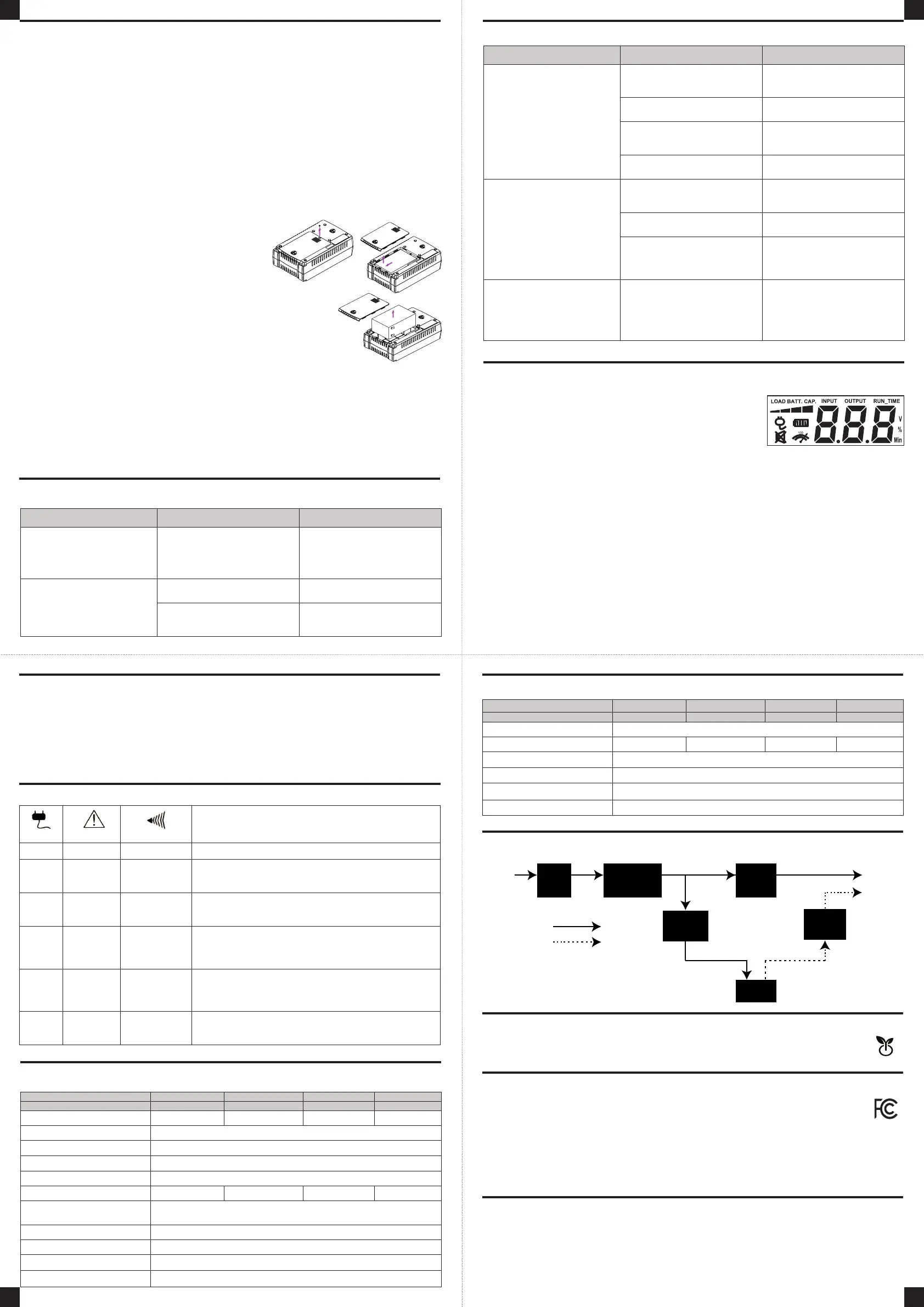
TO REPLACE THE BATTERY
1. Turn o and unplug all connected equipment.
2. Unplug it from the AC power source.
3. Turn the UPS upside down.
4. Remove the 1 retaining screw.
5. Slide the battery compartment cover completely
o of the unit.
6. Remove the battery from the compartment.
7. Disconnect the battery cables from the battery.
8. Install the replacement battery by connecting the red
wire and black wire to the positive (+) and negative (-)
terminal of the battery.
9. Put the battery back into the compartment.
10. Slide back the battery compartment cover and tighten the retaining screw.
11. Charge the unit for 8 hours to fully charge the battery.
REMINDER: Batteries are considered HAZARDOUS WASTE and must be disposed of properly.
Most retailers that sell lead-acid batteries collects used batteries for recycling, as required by
local regulations.
The LCD display indicates a variety of UPS operation-
al conditions. All descriptions apply when the UPS is
plugged into an AC outlet and turned on or when the
UPS is on battery.
Series CP825AVRLCDG CP685AVRLCDG CP600AVR CP685AVR
Model CP825AVRLCDa CP685AVRLCDGa CP800AVRa CP685AVRa
Capacity 825 VA/450 W 685 VA/390 W 800 VA/450 W 685 VA/390 W
Nominal Input Voltage 120 V
Input Frequency 60 Hz ± 3 Hz
On-Battery Output Voltage 120 VAC ± 5%
On-Battery Output Frequency 60 Hz ± 3 Hz
Max. Load for UPS Outlets 825 VA/450 W 685 VA/390 W 800 VA/450 W 685 VA/390 W
Max. Load for Full-time
Surge Protection Outlets
12 Amps
On-Battery Output Wave Form Simulated Sine Wave
Surge Protection 1030 J
Operating Temperature + 32°F to 104° F / 0° C to 40° C
Operating Relative Humidity 0 to 90% non-condensing
DEFINITIONS FOR LED INDICATORS & AUDIBLE ALARMS
POWER WIRING FAULT
ALARM
CONDITION
On O O Normal
On O
Beep
twice every
30 seconds
Utility Failure - Battery Mode: The UPS is providing power to
battery power-supplied outlets from its battery.
On O
Rapid
beeping every
1/2 second
Utility Failure - Low Battery: The UPS is providing battery pow-
er. Rapid beeping indicates the unit will run out of power soon.
On/O
Flash once
every 5
seconds
Constant tone
Battery Mode or AC/Utility Power Mode Overload Fault:
Occurs when connected equipment exceeds the rating of
battery outlets of the unit. Please unplug at least one piece
of equipment from battery outlets..
O
Flash twice
every 5
seconds
Constant tone
Battery Output Short Fault: Please unplug at least one
piece of equipment from battery outlets and turn on the
UPS again. If the fault still exists, please contact Cyber-
Power Systems for support.
On
Flash 3
times every
5 seconds
Constant tone Charger Fault: Contact CyberPower Systems for support.
Series CP825AVRLCDG CP685AVRLCDG CP600AVR CP685AVR
Model CP825AVRLCDa CP685AVRLCDGa CP800AVRa CP685AVRa
Size (W x H x D) 11.02” x 6.81” x 3.47” / (100 x 280 x 355 mm)
Net Weight 12.74 lbs. 11.62 lbs. 12.74 lbs. 11.62 lbs.
Typical Battery Recharge Time 8 hours typical from total discharge
Typical Battery Life 3 to 6 years, depending on number of discharge/recharge cycles
Recommended Battery Sealed Maintenance Free Lead Acid Battery
Safety Approvals UL1778(UPS), cUL107, FCC/DoC Class B
SYSTEM FUNCTION BLOCK DIAGRAM
Input Output
Battery Mode
Normal Mode
EMI
Filter
Surge
Suppressor
Inverter
Charger
AC / DC
Battery
AVR
 Loading...