IM 1255-1 • INTELLIGENT SYSTEM MANAGER 2 www.DaikinApplied.com
Installation
The System Manager shall be located in a conditioned space
that is easily accessible. Allow for space around the system
manager for air ow circulation to reject heat. The VESA
mounts on the display bracket allows the system Manager
to be attached to the back of the monitor via VESA mounting
screws. The display bracket can also be mounted on a wall,
with the monitor attached to the front.
1. Fasten the display bracket to the back of the monitor
using the screws.
2. Fasten wall mounting screws and anchors into a wall,
leaving space to attach the display bracket. Slide the
display bracket mounting holes onto the screws and
fasten. It is recommended that at least one screw should
be mounted in a wall stud.
NOTE: The wall mounting screws and anchors are not
included.
3. Slide the system manager into the display bracket, the
rubber feet should be facing away from the monitor.
4. Connect cables.
a. VGA – System Manager to Monitor
b. USB – System Manager to touch screen monitor
c. (2) Power Supply – Barrel Screw Connector to
System Manager and touchscreen monitor
5. Connect the BACnet MS/TP twisted pair wire to the
BACnet
®
MS/TP terminal maintaining polarity throughout
the daisy-chain.
6. The Intelligent Systems automatically starts when the
System Manager has power; once the BACnet MS/TP
network is connected the system will run appropriately.
Refer to OM 1254 for user operation and system
conguration.
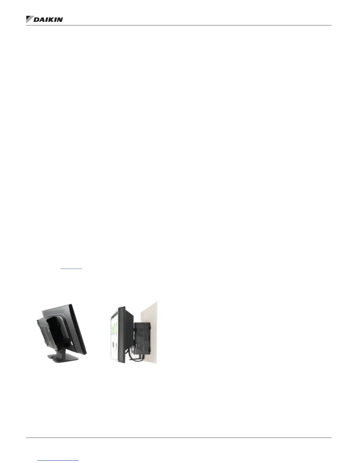
Figure 2: System Manager VESA mounted on the touch
screen monitor (monitor stand not included)
BACnet Module LED Sequencing
The BACnet Module LEDs will go through a particular
sequence on power-up and when the Intelligent Systems
Application starts. These sequences occur when the BACnet
MS/TP network isn’t connected, but showing the BACnet
Module working appropriately.
On Power-Up
1. All LEDs are ON.
2. LED D1 is OFF immediately after power, then short pulse
about every 4 seconds. This is a request to the Intelligent
Systems computer to send conguration data to the
BACnet module. The other 3 LEDs remain ON until the
BACnet module is congured by the Intelligent Systems
Application.
On Intelligent Systems Application Start-Up
1. LED D2 short pulse indicating Intelligent Systems
Application is sending conguration data to the BACnet
module.
2. LED D3 starts fast icker as the BACnet module is now
sending Poll for Master (PFM) requests to the BACnet
network.
3. LED D4 remains ON steady indicating no network trafc
is received.
4. LED D2 ickers about every 8 seconds as Intelligent
Systems sends Who-IS requests to wake up devices that
may connect to the MS/TP network.
 Loading...