4 Instructions RI8PG202 © Danfoss 02/2014 AK-CC 250A
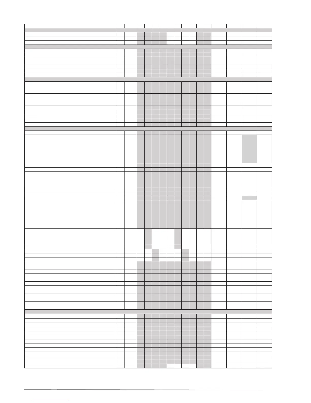
1 2 3 4 5 6 7 8 9 10
Fan
Fan stop at cutout compressor F01 no yes no
Delay of fan stop F02 0 min 30 min 0 min
Fan stop temperature (S5) F04 -50.0°C 50.0°C 50.0°C
HACCP
Actual temperature measurement for the HACCP function h01
Last registered peak temperature h10
Selection of function and sensor for the HACCP function. 0 = no
HACCP function. 1 = S4 used (maybe also S3). 2 = S5 used
h11 0 2 0
Alarm limit for the HACCP function h12 -50.0°C 50.0°C 8.0°C
Time delay for the HACCP alarm h13 0 min. 240 min. 30 min.
Select signal for the HACCP function. S4% (100% = S4, 0% = S3) h14 0% 100% 100%
Real time clock
Six start times for defrost.
Setting of hours.
0=OFF
t01-t06 0 hours 23 hours 0 hours
Six start times for defrost.
Setting of minutes.
0=OFF
t11-t16 0 min 59 min 0 min
Clock - Setting of hours *** t07 0 hours 23 hours 0 hours
Clock - Setting of minute *** t08 0 min 59 min 0 min
Clock - Setting of date *** t45 1 31 1
Clock - Setting of month *** t46 1 12 1
Clock - Setting of year *** t47 0 99 0
Miscellaneous
Delay of output signals after start-up o01 0 s 600 s 5 s
Input signal on DI1. Function:
0=not used. 1=status on DI1. 2=door function with alarm when
open. 3=door alarm when open. 4=defrost start (pulse-pres-
sure). 5=ext.main switch. 6=night operation 7=change refer-
ence (activate r40). 8=alarm function when closed. 9=alarm
function when open. 10=case cleaning (pulse pressure).
11=forced cooling at hot gas defrost.
o02 1 11 0
Network address (0=o) o03 0 240 0
Access code 1 (all settings) o05 0 100 0
Used sensor type. See page 6.
Pt: Pt 1000 Ω @ 0°C
P01: PTC 1000 Ω (nominal 990 Ω) = EKS 111
P02: PTC 1000 Ω @ 25°C (nominal 1000 Ω)
o06 Pt P02 Pt
Display step = 0.5 (normal 0.1 at Pt sensor) o15 no yes no
Max hold time after coordinated defrost o16 0 min 60 min 20
Select signal for display view. S4% (100%=S4, 0%=S3) o17 0% 100% 100%
Input signal on DI2. Function:
(0=not used. 1=status on DI2. 2=door function with alarm when
open. 3=door alarm when open. 4=defrost start (pulse-pres-
sure). 5=ext. main switch 6=night operation 7=change refer-
ence (activate r40). 8=alarm function when closed. 9=alarm
function when open. 10=case cleaning (pulse pressure).
11=forced cooling at hot gas defrost.). 12=coordinated defrost)
o37 0 12 0
Conguration of light function (relay 4)
1=ON during day operation. 2=ON / OFF via data communica-
tion. 3=ON follows the DI-function, when DI is selected to door
function or to door alarm
o38 1 3 1
Activation of light relay (only if o38=2) o39 OFF ON OFF
Rail heat On time during day operations o41 0% 100% 0
Rail heat On time during night operations o42 0% 100% 0
Rail heat period time (On time + O time) o43 6 min 60 min 10 min
Case cleaning. 0=no case cleaning. 1=Fans only. 2=All output
O.
*** o46 0 2 0
Selection of EL diagram. See overview page 2 * o61* 1 10 1
Download a set of predetermined settings. See overview
previous page.
* o62* 0 6 0
Access code 2 (partly access) *** o64 0 100 0
Save the controllers present settings to the programming key.
Select your own number.
o65 0 25 0
Load a set of settings from the programming key (previously
saved via o65 function)
o66* 0 25 0
Replace the controllers factory settings with the present set-
tings
o67 OFF On OFF
Service
Status codes are shown on page 5 S0-S33
Temperature measured with S5 sensor *** u09
Status on DI1 input. on/1=closed u10
Temperature measured with S3 sensor *** u12
Status on night operation (on or o) 1=closed *** u13
Temperature measured with S4 sensor *** u16
Thermostat temperature u17
Read the present regulation reference u28
Status on DI2 output. on/1=closed u37
Temperature shown on display u56
Measured temperature for alarm thermostat u57
Status on relay for cooling ** u58
Status on relay for fan ** u59

 Loading...


