12 Instructions RI8LN802 © Danfoss 2/2012 AK-CC 550
Fault message
In an error situation the LED’s on the front will flash and the alarm relay will be
activated. If you push the top button in this situation you can see the alarm
report in the display.
There are two kinds of error reports - it can either be an alarm occurring dur-
ing the daily operation, or there may be a defect in the installation.
A-alarms will not become visible until the set time delay has expired.
E-alarms, on the other hand, will become visible the moment the error occurs.
(An A alarm will not be visible as long as there is an active E alarm).
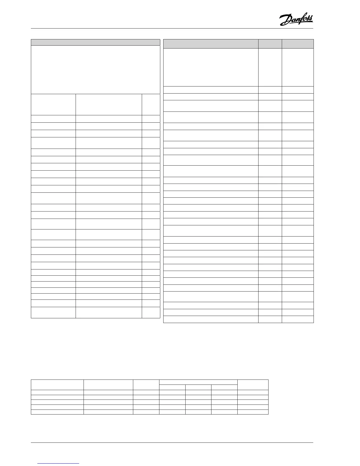
Here are the messages that may appear:
Code / Alarm text via
data communication
Description
Alarm
relay
groups
(P41)
A1/--- High t.alarm High temperature alarm
1
A2/--- Low t. alarm Low temperature alarm
2
A4/--- Door alarm Door alarm
8
A5/--- Max hold time The ”o16” function is activated during a
coordinated defrost
16
A10/--- Inject prob. Control problem
64
A11/--- No Rfg. sel. No refrigerant selected
64
A13/--- High temp S6 Temperature alarm. High S6
1
A14/--- Low temp S6 Temperature alarm. Low S6
2
A15/--- DI1 alarm DI1 alarm
8
A16/--- DI2 alarm DI2 alarm
8
A45/--- Standby mode Standby position (stopped refrigera-
tion via r12 or DI input)
-
A59/--- Case clean Case cleaning. Signal from DI input
-
A74/--- AD fault Error in the adaptive defrost function
16
A75/--- AD Iced Evaporator is iced up. Reduction of
air flow
16
A76/--- AD not defr. Defrost of evaporator is not
satisfactory
16
E1/--- Ctrl. error Faults in the controller
32
E6/--- RTC error Check clock
32
E20/--- Pe error Error on pressure transmitter Pe
64
E23/--- S1 error
Error on S1 sensor 4
E24/--- S2 error Error on S2 sensor 4
E25/--- S3 error Error on S3 sensor 4
E26/--- S4 error Error on S4 sensor 4
E27/--- S5 error Error on S5 sensor 4
E28/--- S6 error Error on S6 sensor 4
E37/--- S5 error B Error on S5B sensor
4
---/--- Max Def.Time Defrost stopped based on time instead
of, as wanted, on temperature
16
Settings from
System manager
Settings from
AKM (AKM destination)
Log Alarm relay Send via
Network
Non High Low-High
High 1 X X X X
Middle 2 X X X
Low 3 X X X
Log only X
Disabled
Additional information:
Manual RS8EN
Data communication
The importance of individual alarms can be defined with a setting. The setting
must be carried out in the group "Alarm destinations"
*) Emergency cooling will take effect when there is lack of signal from a defined
S3 or S4 sensor. The regulation will continue with a registered average cutin
frequency. There are two registered values – one for day operation and one for
night operation.
Operating status (Measurement)
The controller goes through some regulating situa-
tions where it is just waiting for the next point of the
regulation. To make these “why is nothing happening”
situations visible, you can see an operating status on
the display. Push briefly (1s) the upper button. If there is
a status code, it will be shown on the display. The indi-
vidual status codes have the following meanings:
Ctrl. state:
(Shown in all
menu displays)
Normal regulation S0 0
Waiting for end of the coordinated defrost S1 1
When the compressor is operating it must run for at least
x minutes.
S2 2
When the compressor is stopped, it must remain stopped
for at least x minutes.
S3 3
The evaporator drips off and waits for the time to run out S4 4
Refrigeration stopped by main switch. Either with r12 or
a DI-input
S10 10
Refrigeration stopped by thermostat S11 11
Defrost sequence. Defrost in progress S14 14
Defrost sequence. Fan delay — water attaches to the
evaporator
S15 15
Refrigeration stopped due to open ON input or stopped
regulation
S16 16
Door is open. DI input is open S17 17
Melt function in progress. Refrigeration is interrupted S18 18
Modulating thermostat control S19 19
Emergency cooling due to sensor error S20 20
Regulation problem in the injections function S21 21
Start-up phase 2. Evaporator being charged S22 22
Adaptive control S23 23
Start-up phase 1. Signal reliability from sensors is
controlled
S24 24
Manual control of outputs S25 25
No refrigerant selected S26 26
Case cleaning S29 29
Forced cooling S30 30
Delay on outputs during start-up S32 32
Heat function r36 is active S33 33
Other displays:
The defrost temperature cannot be displayed. There is
stop based on time
non
Defrost in progress / First cooling after defrost -d-
Password required. Set password PS
Regulation is stopped via main switch OFF
DE-DB

 Loading...


