4 Instructions RI8SR1ML © Danfoss 01/2019 AK-PC 572
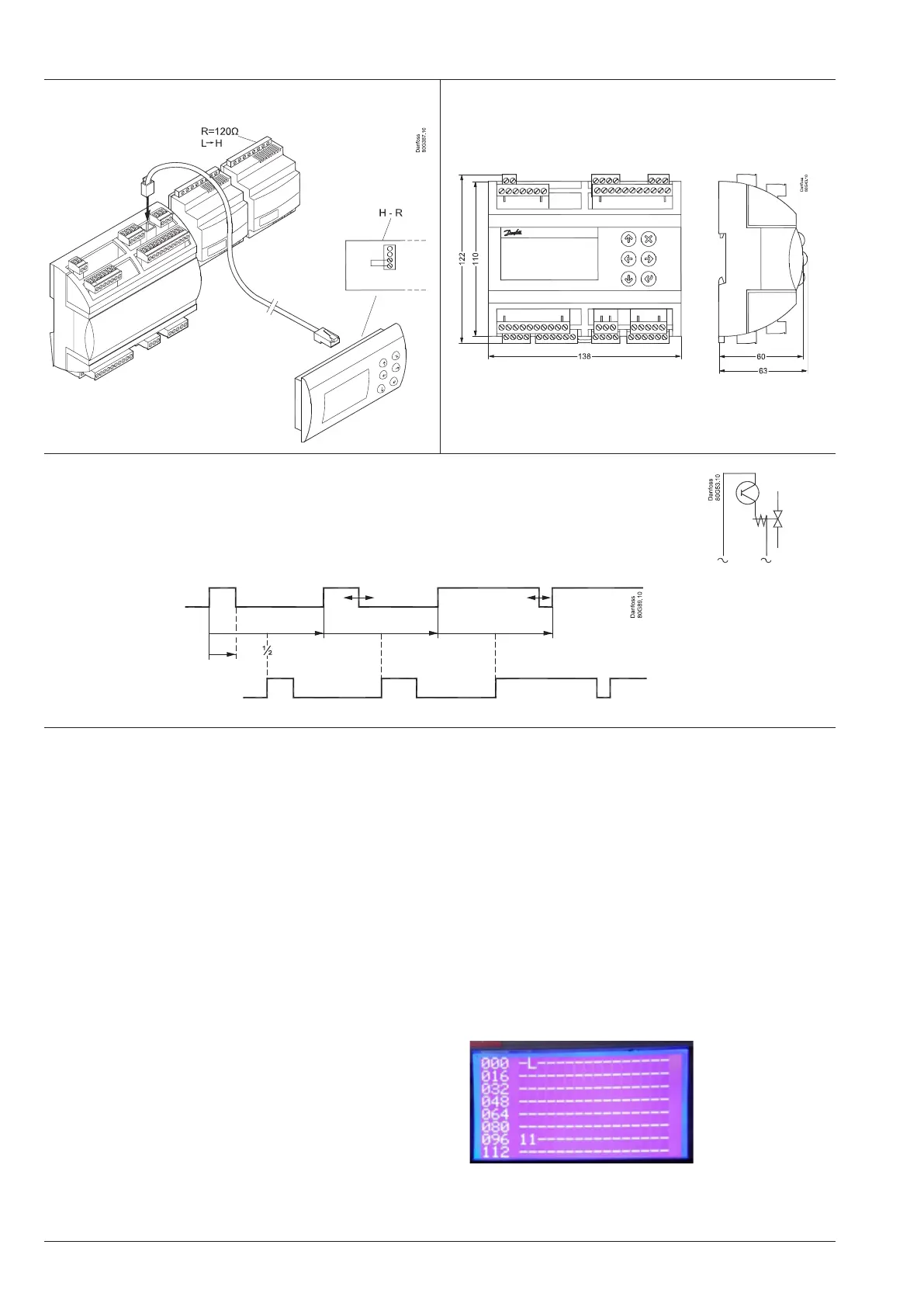
External display Dimensions
Bitzer CRII
The pulse signal can also be used to control one of the CRII with 2 unloaders (4 cylinders version).
Compressor capacity can be controlled from 10 to 100% depending on the pulsation of the unloaders.
The unloaders are connected to DO5 and DO6.
Connect compressor relay to DO-MT1.
Unloader 2 follows unloader 1
but is offset a ½ period.
Unloader 1
Unloader 2
Important
Read the following before you connect the controller and the two
valve modules to the supply voltage.
Both valve modules are factory set with the same address.
In order to give each module the correct address, you must follow
this procedure:
1. On the two valve modules, remove the terminals with power
supply.
(The power supply is connected later, but in the correct order).
2. Connect the controller to the power supply
3. Check that the main switch is OFF
4. HP module: Mount the terminal with power supply
5. Wait 5 seconds
6. Receiver module: Mount the terminal with power supply.
Wait 5 seconds
All modules now have power supply and the two modules each
have their own address:
96 for the HP module
97 for the receiver module.
The addresses will only be used internally between the three
modules.
If anything has gone wrong, the two valve modules will have acti-
vated the function "EXD reset node ID" and the procedure must be
repeated.
Resetting incorrect addresses in the valve modules:
1. Connect all three modules to the power supply
2. Find the following setting on the controller module
"System"> "Network" > "EXD reset node id's"
3. Set the value to 20
4. Cut out the supply voltage to the valve modules
5. Repeat the earlier procedure.
If you wish to check the addresses of the two valve modules, you
should carry out the following:
1. Connect all modules to the power supply.
2. Immediately press on both the "X" and "Enter" buttons while the
controller is starting up.
3. Find the display "CAN SETTINGS" > "ACTIVE NODES"
The two 1-digits represent the addresses 96 and 97 respec-
tively.
If you remove the connection to a valve module, the display of
the address will also disappear.

 Loading...


