ENGLISH
Safety Note
To avoid injury of persons and
damages to the device, it is absolutely
necessary to read and observe these
instructions carefully.
Necessary assembly, start-up, and maintenance
work must be performed by qualified and
authorized personnel only.
Please comply with the instructions of the
system manufacturer or system operator.
Do not remove the cover before the
power supply is fully switched off.
Disposal instruction
This product should be dismantled
and its components sorted, if possible,
in various groups before recycling or
disposal.
Always follow the local disposal regulations.
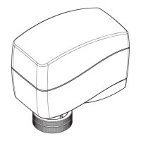
Mounting ➊
In case of ship applications (on water) actuator
should be mounted with the valve stem in
either 30° above horizontal position or pointing
upwards.
In case of building applications actuator should
be mounted with the valve stem in either
horizontal position or pointing
upwards.The actuator is fixed to the valve body
by means of a ribbed nut which requires no
tools for mounting. The ribbed nut should be
tightened by hand.
Installation ❷
1. Check the valve neck. The actuator should
be in steam up position (factory setting).
Ensure that the actuator is mounted securely
on the valve body
2. Wire the actuator according to the wiring
diagram
3 The direction of stem movement can be
observed on the position indicator ①
Wiring ❸
Red 24 VAC
Reset
2 V...---V 0V...---V
Direct Inverse
--- Sequential
0(2)...5(6)V 5(6)...10V
U I
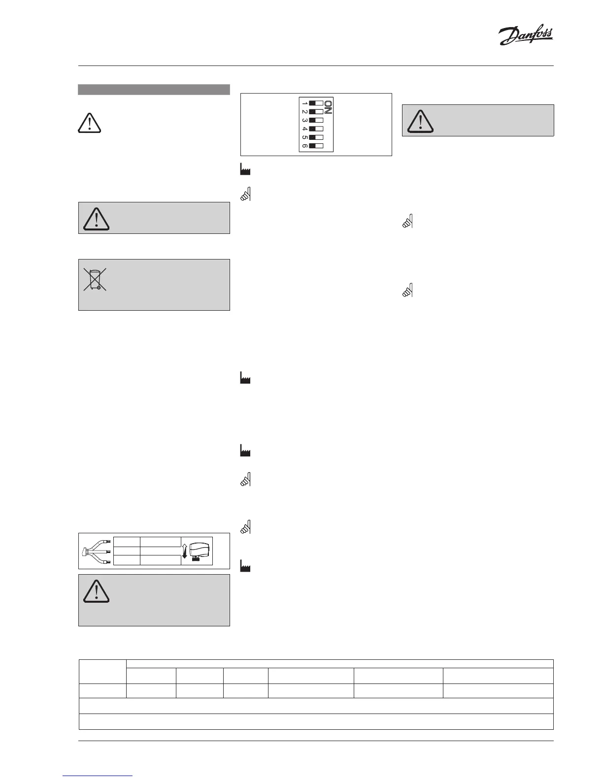
Factory settings:
ALL switches are on OFF position!
NOTE: All combinations of DIP switches are
allowed. All functions that are selected are
added consecutively.
SW1: Reset ②
After the actuator has been connected to
power supply, the actuator will start the self-
adjustment procedure. The indicator LED ①
flashes until self adjustment is finished. The
duration depends on the spindle travel and will
normally last a few minutes. The stroke length
of the valve is stored in the memory after self
adjustment has been completed. To restart self
adjustment, change the position of the RESET
switch (switch No.1). If the supply voltage is
switched off or falls below 80 % in more than
0.1 s, the current valve position will be stored
in the memory and all data remain saved in the
memory also after a power supply cut-out.
SW2: 2-10 V/0-10 V ③
Factory setting is:
2-10 V.
SW3: Direct/Inverse ④
The actuator can be set for the spindle to
travel downwards on the rising control signal
(DIRECT), OR for the spindle to travel upwards
on the rising control signal (INVERSE)
Factory setting is:VI.KU.M6.9ODIRECT
SW4: ---/Sequential ⑤
NOTE: This combination works in
combination with switch No.5: 0(2)-5(6) V/5(6)-
10 V.
SW5: 0(2)-5(6) V/5(6)-10 V ⑥
NOTE: This function is available if switch
No.4: ---/Sequential is set.
SW6: U/I ⑦
Factory setting:
voltage control signal (2-10 V).
Manual override
(for service purposes only)
Do not manually operate the drive
under power!
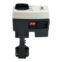
AME 130, AME 140 ➎
① Remove the cover
② Insert the Allen key 6 into the spindle
③ Press and hold the button (on the bottom
side of the actuator) during manual override
④ Pull out the tool
⑤ Replace cover
Remark: A ‘click’ sound after energising
the actuator means that the gear wheel has
jumped into normal position.
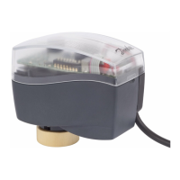
AME 130H, AME 140H ❻
Press and hold the button ① (on the bottom
side of the actuator) during manual override.
Remark: A ‘click’ sound after energising
the actuator means that the gear wheel has
jumped into normal position.
Function test
The light emitting diode (LED) ❹① indicates
whether the actuator is in operation or not, the
operating status, and failures, if any.
• No light
- no operation or no power supply
• Constant light
- normal operation
• Flashing light (1 Hz)
- self-adjusting mode
• Flashing light (~ 3 Hz):
- power supply too low
- initial self-adjusting time to short due too
short valve’s stroke must last more than 12
sec.
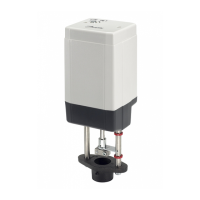
Dimensions ❼
Part Name
部件名称
Hazardous Substances Table/有害物质含量表
Lead (Pb)
铅 (Pb)
Mercury (Hg)
汞 (Hg)
Cadmium (Cd)
镉 (Cd)
Hexavalent Chromium (Cr(VI))
六价铬 (Cr(VI))
Polybrominated biphenyls (PBB)
多溴联苯 (PBB)
Polybrominated diphenyl ethers (PBDE)
多溴二苯醚 (PBDE)
Connecting nut
连接螺母
X O O O O O
O: Indicates that this hazardous substance contained in all of the homogeneous material for this part is below the limit requirement in GB/T 26572;
O: 表示该有害物质在该部件所有均质材料中的含量均在GB/T 26572规定的限量要求以下。
X: Indicates that this hazardous substance contained in at least one of the homogeneous material for this part is above the limit requirementw in GB/T 26572;
X: 表示该有害物质至少在该部件的某一均质材料中的含量超出GB/T 26572规定的限量要求。
 Loading...