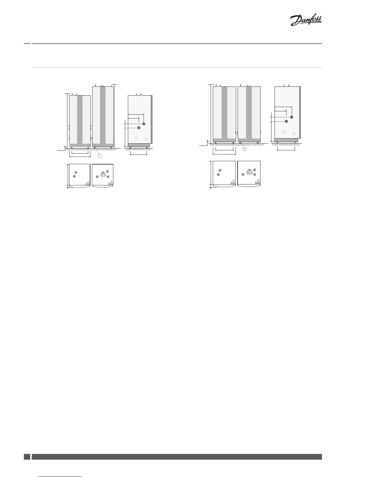
EasyManuals Logo
Home>Danfoss>Heat Pump>DHP-H

Danfoss DHP-H Installation Guide

Danfoss DHP-H
64 pages
To Next Page IconTo Next Page
To Previous Page IconTo Previous Page
Page #18 background imageLoading...
Page #18 background image
4.1 DWH
DHP-L with DWH 300 DHP-L with DWH 200
455
596
610
80
1845 (±10)
4
5
3
7 8
9
10
11
5
690
110
528
300
440
1
2
6
1538 (±10)
40±10
6
1538 (±10)
455
596
690
40±10
110
528
610
80
300
440
1
2
6
4
5
3
7 8
9
10
11
5
6
1 Brine in, 28 Cu
2 Brine out, 28 Cu
3 Heating system supply pipe, 22 Cu: 4-10 kW, 28 Cu: 12-16 kW
4 Heating system return pipe, 22 Cu: 4-10 kW, 28 Cu: 12-16 kW
5 Lead-in for supply, sensor and communication cables
6 Return line from water heater to heat pump Ø 22 mm
7 Hot water Ø 22 mm
8 Cold water Ø 22 mm
9 Supply line from heat pump (diam) 22 mm
10 Connection for bleed valve, 22 Cu
11 Combined temperature and pressure relief valve
The brine pipes can be connected on either the left or right-hand sides of the heat pump.
Installation Guide
Domestic heat pumps
VMGFQ102 Danfoss Heating Solutions
18

Other manuals for Danfoss DHP-H

Questions and Answers:

Question and Answer IconNeed help?

Do you have a question about the Danfoss DHP-H and is the answer not in the manual?

Danfoss DHP-H Specifications

General IconGeneral
BrandDanfoss
ModelDHP-H
CategoryHeat Pump
LanguageEnglish

Related product manuals