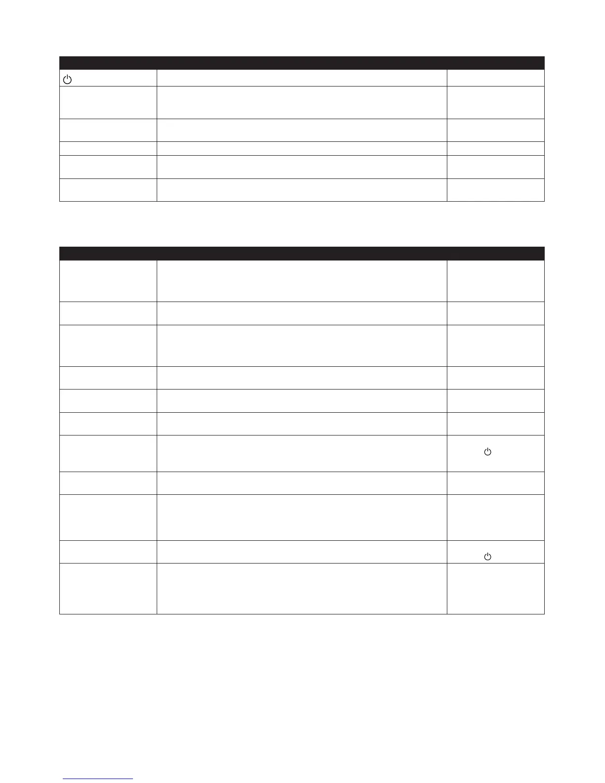
Sub menu INFORMATION -> OPERATION
Used to select operating mode.
Menu selection Meaning Factory setting
(OFF)
The installation is off. Any active alarms reset. -
AUTO Automatic operation with both heat pump and auxiliary heater permitted. If the
number of power stages for auxiliary heating are set to zero (SERVICE -> AUX.
HEAT -> MAX STAGE) only AUTO or OFF can be selected as operating mode.
-
HEATPUMP Operation with only heat pump permitted. NOTE! No peak heating charging
(legionella function) with only heat pump operation.
-
ADD. HEAT Operation with only auxiliary heater permitted. -
HOT WATER Operation with heat pump for hot water production and auxiliary heater during
peak heating charging (legionella function).
-
MANUAL TEST Only appears when MANUAL TEST in the SERVICE menu is active. Outputs con-
trolled manually.
-
Sub menu INFORMATION -> HEAT CURVE
Used to change settings for the heat curve.
Menu selection Meaning Factory setting
CURVE Calculated supply temperature at 0°C outdoor temperature. Shown as a graph
that also shows MIN and MAX values.
40°C
(during under floor heat-
ing 30°C)
(interval: 22°C / 56°C)
MIN Minimum permitted supply temperature, if the temperature for heat-stop has
been reached and the heat pump has stopped.
10°C
(interval: 10°C / 50°C)
MAX Maximum permitted supply temperature. 55°C
(during under floor heat-
ing 45°C)
(interval: 40°C / 85°C)
CURVE 5 LocalincreaseorreductionofCURVEatanoutdoortemperatureof+5°C.Shown
in the graph for CURVE.
0°C (interval: -5°C / 5°C)
CURVE 0 Local increase or reduction of CURVE at an outdoor temperature of 0°C. Shown
in the graph for CURVE.
0°C (interval: -5°C / 5°C)
CURVE -5 Local increase or reduction of CURVE at an outdoor temperature of -5°C. Shown
in the graph for CURVE.
0°C (interval: -5°C / 5°C)
HEATSTOP Maximum outdoor temperature when heat production is permitted.
If HEAT STOP applies, the outdoor temperature must drop 3°C below the setting
before HEAT STOP stops.
17°C
(interval:
, 0°C / 40°C)
REDUCTION Only appears if the tariff control function has been activated. Lowering set room
temperature. Active at 10 kohm connection at EVU input.
2°C (interval: 1°C / 10°C)
ROOM FACTOR Only displayed if an accessory Room temperature sensor is installed.
Determines how large an impact the room temperature is to have when calcu-
lating the supply temperature. For underfloor heating we recommend a setting
between 1-3 and for radiator heating between 2-4.
2 (interval: 0 / 4)
(0 = no impact,
4 = large impact)
POOL
(Expansion card)
Only appears if POOL is selected. The temperature in the pool is controlled by a
separate sensor regardless of the heating and hot water system.
20°C
(interval:
, 5°C / 40°C)
POOL HYSTERESIS
(Expansion card)
Only appears if POOL is selected. In simple terms, the POOL HYSTERESIS is the
temperature interval between start and stop for pool heating. If the difference
between the actual supply temperature to pool and the calculated supply tem-
perature is too great, either the integral value is set to start value A1 (the heat
pump starts) or the value is set to 0 (stops the heat pump).
2°C (interval: 1°C / 10°C)
 Loading...