EKC 414A1 Instructions RI8JN253 © Danfoss 05/2005 9
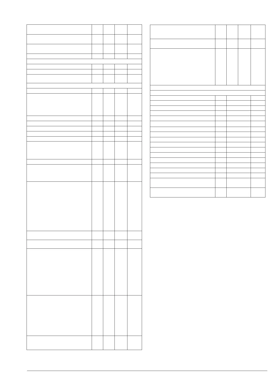
Average opening degree.
Should only be changed by trained staff
n16 10% 75% 30.0
Start-up time for signal reliability
Should only be changed by trained staff.
n17 5% 70% 30.0
Stability factor for superheat control.
Changes should only be made by trained staff
n18 0 10 4
Forced closing. AKV valve shut in pos. ON
n36 OFF ON OFF
Fan
Fan stop on compressor cut out
F01 no yes no
Delayed fan stop when compressor is cut out
F02 0 min 30 min 0
Safety function. The fan stops if the S5 tem
-
perature reaches this value
F04 -50.0
50.0/
off
50.0
Miscellaneous
Delay of output signal after start-up
o01 0 sec. 600 sec 5
Define digital input signal (DI:
OFF=not used, 1=Door alarm, 2=defrost start,
3=Night operation, 4=External start/stop, 5 =
Coordinated defrost with cable connections,
6 = door function
o02 OFF 6 0
Network address (range = 0-60) o03 0 990 0
ON/OFF switch (service-pin message)
o04 OFF ON OFF
Access code
o05 OFF 100 OFF
Used sensor type for S3, S4 and S5 (Pt / PTC)
o06 Pt Ptc 0/Pt
Set supply voltage frequency
o12 50 Hz 60 Hz 50
Define digitalt output signal (DO:
0=not used
Coordinated defrost with cable connections:
1=Master, 2= Slave
o13 0 2 0
Max. standby time after coordinated defrost
o16 1 min 30 min 20
Display S4 % (S
out
)
0%=S3 (S
in
)
100%=S4 (S
out
)
The display temperature can be seen in u56
o17 0% 100%
100
Manual control of outputs:
OFF=No override
1: Compressor reay is ON (railheat relay = ON)
2: Defrost relay is ON
3: Fan relay is ON
4: Alarm relay is OFF (Railheat relay = on)
5: DO output is ON
6: AKV output is ON
7: Light relay is ON (Railheat relay = on)
When manual control is terminated, the set
-
ting must be changed to OFF
o18 OFF 7 OFF
Pressure transmitter working range – min.
value
020 -1 bar 5 bar -1
Pressure transmitter working range – max.
value
021 6 bar 36 bar 12
Inject-ON definition
When the ON input is cut out refrigeration is
stopped.
Here you define how the fan relay and the
alarm function are to act:
1 = Fan relay = ON, alarm monitoring active
2 = Fan relay = OFF, alarm monitoring active
3 = Fan relay = OFF, no alarm monitoring
4 = Fan relay = ON, no alarm monitoring
5 to 8= as 1 to 4, but without connection to
terminal 40-41.
o29 1 8 5
Refrigerant setting
1=R12. 2=R22. 3=R134a. 4=R502. 5=R717.
6=R13. 7=R13b1. 8=R23. 9=R500.
10=R503. 11=R114. 12=R142b. 13=User
defined. 14=R32. 15=R227. 16=R401A.
17=R507. 18=R402A. 19=R404A. 20=R407C.
21=R407A. 22=R407B. 23=R410A. 24=R170.
25=R290. 26=R600. 27=R600a. 28=R744.
29=R1270. 30=R417A
o30 0 30 0
Rail heat during day operation.
Setting of ON period in percentage of the
time in ”o43”
o41 0% 100% 100
Rail heat during night operation.
Setting of ON period in percentage of the
time in ”o43”
o42 0% 100% 100
Rail heat
Time period for the aggregate ON/OFF time
o43 6 min 60 min 10
Rail heat definition
0 = no rail heat relay
1 = alarm relay changed into rail heat relay
2 = compressor relay changed into rail heat
relay
3 = no function
4 = no function
5 = light relay changed into rail heat relay
o68 0 5 0
Service
The following readouts can be performed via the belonging parameter
Defrost sensor S5 S
def
u09 °C
Status on DI-input u10
Defrost time
u11 min.
Air temperature S3 (S
in
) u12 °C
Status on night operation (on or off)
u13
Status on ON-input
u14
Status on DO-output
u15
Air temperature S4 (S
out
) u16 °C
Thermostat temperature
u17 °C
Thermostat cut-in time
u18 min.
Temperature at S2
u20 °C
Superheat
u21 K
Superheat reference
u22 K
AKV valve’s actual opening degree
u23 %
Evaporating pressure
u25 bar
Evaporating temperature
u26 °C
Weighted S3/S4 temperature shown in the
display
u56 °C
Weighted S3/S4 temperature used by the
alarm function
u57 °C
Factory setting
If you need to return to the factory-set values, it can be done in this way:
- Cut out the supply voltage to the controller
- Keep both buttons depressed at the same time as you reconnect the supply voltage
 Loading...